 SWBTEC


Slewing Drive Selection: Loads, Motion, And Fit
A rotating platform has to do more than turn. It must carry the equipment above it, resist the moment created by an off-center load, and move at a controlled speed. A slewing drive brings the bearing and drive mechanism into one assembly, giving the machine builder a compact way to handle these jobs together.
That integration is useful, but the name alone says little about what the unit can safely do. The loads, motion cycle, input arrangement, mounting structure, and holding requirements still have to be defined for the actual machine.
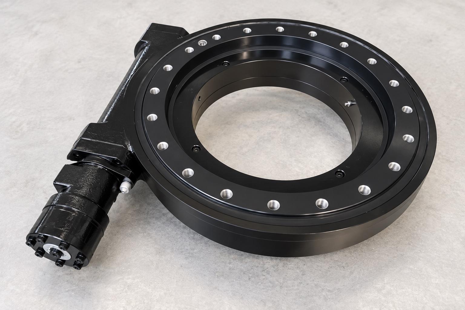
What Is Inside A Slewing Drive?
The bearing section connects the fixed structure to the rotating one. Its rings and rolling elements carry axial force, radial force, and overturning moment. A transmission then applies torque to turn one ring relative to the other. The housing locates and protects the transmission, while mounting holes connect the assembly to the surrounding structure.
In a worm gear design, power enters through a worm shaft. The worm engages teeth associated with the rotating ring, producing a geared reduction before the output moves. This is the type of integrated drive included in Slewbearingtec’s product range. The exact motor, reducer, brake, encoder, and other accessories depend on the specified supply scope; they should not be assumed to come with every drive.
A bare slewing bearing is different. It provides the load-carrying and rotating interface, but the machine builder must arrange the drive, its gear mesh, and any necessary protection separately. This distinction matters when comparing quotations: two items called a “slewing drive” may include different components.
Follow The Load, Then The Motion
Start with the forces acting at the rotation interface. Record axial and radial forces together with the overturning moment for each operating condition. An offset payload, acceleration, wind, or a change in machine attitude can shift the controlling load case. The largest values may occur at different times, so a list of isolated maximums is less useful than a set of realistic load combinations.
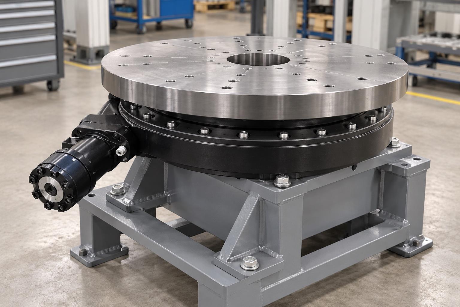
Next describe how the output actually moves. Does it rotate continuously, swing through a limited angle, or make short positioning moves? Note the output speed, travel angle, starts and stops, reversals, operating hours, and duty cycle. A drive that meets a brief peak torque demand may still be unsuitable for sustained operation if heat generation and lubrication cannot be managed.
Torque figures need careful labels. Running torque, starting or peak torque, holding torque, and external back-driving torque answer different questions. A reduction ratio describes the relationship between input and output speed; by itself it does not establish efficiency, backlash, positioning accuracy, or safe holding ability.
Why The Worm Gear Layout Needs A Holding Check
Worm gearing can provide a large reduction in a compact arrangement, which makes it a practical candidate for slow, loaded rotation. Its sliding contact also makes efficiency and temperature important. Frequent movement, high duty cycle, or a demanding ambient environment can change which drive is suitable.
Do not treat “self-locking” as a substitute for a brake assessment. Worm lead angle, friction, wear, lubrication, vibration, and reverse loading all affect whether the output can drive the input backward. If a raised load or a machine position must be held safely after power loss, define the worst external torque and the permitted movement, then specify and verify the appropriate braking or locking function.
Check The Interfaces Before Ordering
The mounting drawing should identify the fixed and rotating sides, bolt pattern, center opening, pilot features, overall envelope, and input orientation. Leave room for the motor or hydraulic connection, cables or hoses, lubrication points, and service access. A housing does not make up for a weak or uneven support structure: mounting stiffness and flatness affect how load reaches the bearing and gearing.
Environmental details belong on the same drawing or specification. Dust, water, corrosion, temperature, impact, and cleaning practices influence seals, lubrication, protection, and maintenance. An enclosed housing reduces direct exposure of the gearing, but enclosure alone does not prove a particular protection level or remove the need for inspection.
For a useful supplier review, send the load combinations, motion cycle, output torque requirements, mounting orientation, available space, input power details, and required behavior during a power or control fault. Ask for the assembly drawing and a clear list of supplied items. Then confirm bearing capacity, gearing, bolts, thermal behavior, lubrication, and braking against the same machine conditions.
The right slewing drive is the one whose complete assembly fits the real duty, interfaces, and safety requirements of the equipment. A compact package simplifies integration only when those boundaries are explicit.
