 SWBTEC


Swing Bearings: How To Match Design To Duty
A crane, excavator, or rotating industrial platform may all use what someone calls a swing bearing. The name tells you that one structure turns relative to another, but it does not identify the bearing's internal design or prove that two rings will fit the same machine. A useful selection starts with the loads, movement, drive layout, and mounting structure. Only then does a catalog family become meaningful.
What A Swing Bearing Does
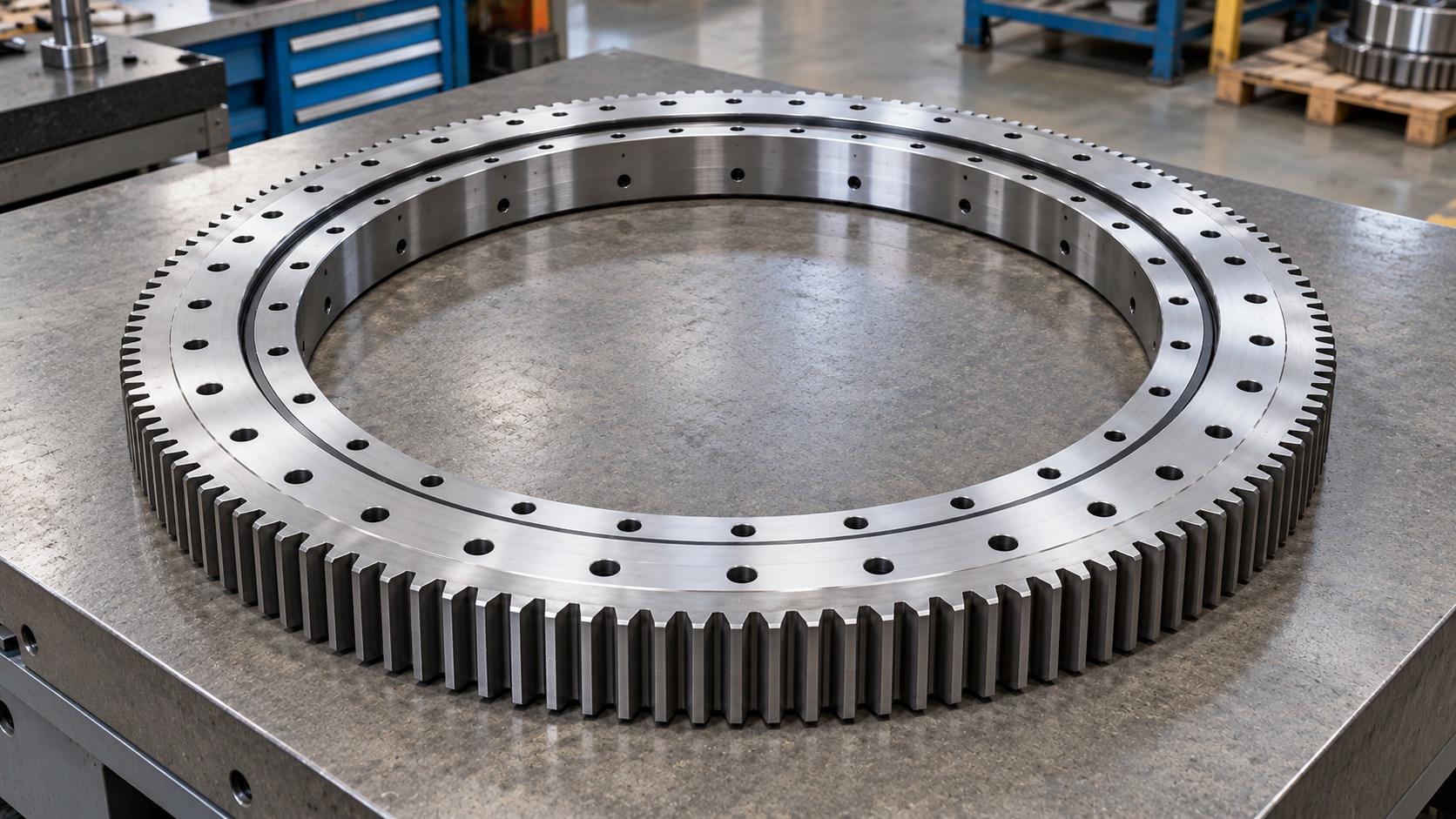
In heavy equipment, swing bearings are generally slewing bearings: large ring-shaped units that connect a stationary structure to a rotating one. Their inner and outer rings, raceways, and rolling elements transfer axial force, radial force, and overturning moment while allowing relative rotation or oscillation. One ring may have gear teeth for a mating pinion; the bearing itself does not supply motor power or braking.
The term can also appear in parts lists for particular machines. If a drawing says “swing bearing,” confirm the component boundary before comparing products. A slewing ring, its pinion, reducer, and motor are different items even though they work together in the same rotation system.
Choose The Rolling-Element Design Around The Load Case
A single-row four-point contact ball design is a compact starting candidate when space is limited and the bearing must carry a combination of axial, radial, and moment loads. Its suitability still depends on the actual load combination. A quoted axial rating alone cannot tell you whether it will handle the machine's overturning moment.
When the required capacity grows and there is room for a deeper section, a double-row ball design may be worth examining. Its two rows create more bearing contact and axial separation, but they also add height and complexity. The two rows should not be assumed to share load equally under every operating condition.
Crossed-roller bearings arrange neighboring cylindrical rollers in alternating directions. This can provide a compact option where combined loads and stiffness matter. Clearance or preload, ring accuracy, and the flatness of the connected structures all affect the result. The words “crossed roller” by themselves are not a precision or service-life guarantee.
Three-row roller bearings separate load paths across multiple roller rows and can be candidates for demanding combinations of force and moment. They also call for a suitably stiff, well-prepared support structure. Adding rows does not correct a flexible mounting frame. Compare these designs under the same load cases, space limits, lifetime target, and installation assumptions rather than ranking them by a single catalog number.
Treat The Gear As A Separate Choice
Internal gear, external gear, and gearless arrangements answer a different question from the rolling-element design: how the machine will transmit rotation. An external-gear ring places the teeth on the outside diameter; an internal-gear ring places them toward the center opening. A gearless ring needs a separate way to drive or position the rotating structure. Slewbearingtec's product range includes all three gear arrangements, along with single-row ball, double-row ball, crossed-roller, and three-row roller options.
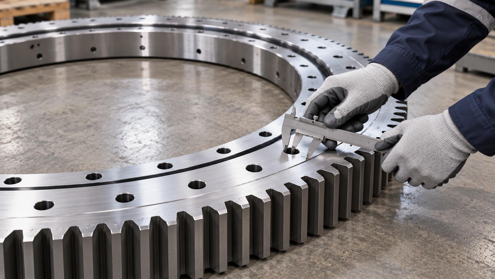
For a geared design, the pinion must match the ring gear. State the gear position, module, tooth count, pressure angle, face width, pinion details, center distance, and required backlash in the design review. Gear tooth capacity, lubrication, and contact pattern need their own checks. A suitable raceway does not make an incompatible gear pair acceptable.
Give The Supplier An Operating Picture
A useful inquiry describes each significant operating condition with the axial force, radial force, and overturning moment that occur together. Include normal work, startup and braking, reversals, shock events, and any parked or exceptional condition relevant to the machine. Record rotation speed or oscillation angle, cycle frequency, operating hours, and intended service life. Small-angle repeated motion deserves particular attention because it repeatedly loads a limited part of the raceway.
The interface matters just as much as the load table. Provide the inside and outside diameter limits, available height, both bolt-hole patterns, locating features, which ring rotates, and the stiffness and flatness expected from the supports. Add the installation orientation, lubrication access, seals, temperature, dust, water, and corrosion exposure. Where accurate positioning matters, state the required running accuracy, clearance or preload, stiffness, and friction limits instead of asking only for a “high-precision” bearing.
Before a final model is approved, the proposed ring should be checked against its own raceway and bolt load limits, duty-cycle life, gear requirements, and the real supporting structure. A replacement also needs controlled drawings and part identification; matching outside diameter alone is insufficient. This keeps the selection tied to the machine that will carry the bearing, rather than to a familiar product name.
