 SWBTEC


Slewing Ring Bearings: Read The Drawing Before Ordering
A slewing ring bearing can look like a straightforward circular part in a product photo. On a machine drawing, it becomes a connection between two structures, a path for combined loads, and sometimes part of the drive. Small differences in that connection can matter more than a matching outside diameter.
If you are comparing slewing ring bearings for a new design or a replacement, put the proposed bearing drawing beside the machine interface drawing. Work through the checks below before approving a model. The aim is to catch mismatches while they are still lines on paper, not after the bearing reaches the workshop.
Identify The Fixed Ring And The Rotating Ring
Start by marking which machine structure is stationary and which one turns. Then mark the corresponding bearing rings. This simple annotation clarifies where each bolt circle connects, how the load passes through the assembly, and where a drive pinion can engage a geared ring.
Do not infer the rotating side from a product photograph. An external gear shows where the teeth are, but it does not tell you which structure your machine will rotate. The application drawing must make that relationship explicit. If a drawing is for a replacement, confirm that its view direction matches the original equipment drawing before comparing the hole patterns.
Compare Both Interfaces, Not Just The Envelope
The outer diameter, inner opening, and overall height are the first dimensions most people notice. They establish whether the ring fits in the available space, but they do not establish whether it can be mounted. Check each bolt circle's pitch diameter, hole count, hole size, and whether the holes are through holes or threaded holes. Also compare any locating shoulders, recesses, and flange details shown on the drawing.
This is especially important when two candidate bearings have similar model names. A mounting hole that lands between the holes in an existing flange cannot be corrected by choosing a different bolt. A bearing that fits the space but interferes with a cover, cable route, or adjacent structure is likewise not a drop-in replacement.
Slewbearingtec's published single-row ball bearing table separates configuration size, mounting size, structural size, and gear data. Treat those as distinct checks on the actual model drawing, rather than assuming that one nominal diameter represents the whole interface.
Read The Gear Callout As Part Of The Drive Layout
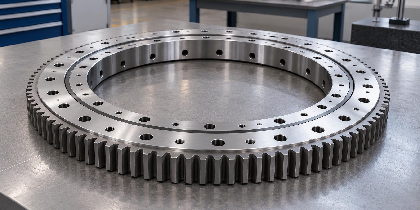
Slewing ring bearings may have external teeth, internal teeth, or no integral gear. The choice changes where the pinion and its support must fit. An external gear needs working space around the outside edge. An internal gear places the mesh within the center opening, where it may compete with shafts, cables, or other equipment. An ungeared bearing still needs a separate plan for rotating or positioning the supported structure.
For a geared design, compare the proposed gear information with the pinion arrangement, including tooth geometry, location, and available clearance. Check the full sweep of nearby components and the route for inspecting and lubricating the mesh. The gear can fit on a drawing yet remain difficult to reach after surrounding guards are installed.
The gear callout should not be used as a shortcut for bearing capacity. The rolling elements and raceways support the imposed loads; the teeth transmit drive force. Both functions need their own review.
Put Real Operating Cases Next To The Drawing
Dimensions alone cannot confirm suitability. The bearing sees axial force along its rotation axis, radial force across it, and overturning moment when the load acts away from the support plane. Record the forces and moment that occur together in each meaningful operating condition, rather than combining unrelated peak values into a fictional case.
Describe how the machine moves as well. Continuous rotation, occasional indexing, and repeated motion through a small angle are different duties. Add starting, stopping, braking, and any parked load that matters. If a pinion drives the ring, include the corresponding drive load and any reversal. A supplier can then assess the proposed raceway, bolted joint, and gear arrangement against the same set of conditions.
The supporting structure belongs in this review. A flexible or uneven mounting face can change how load enters the bearing, even if a catalog capacity appears sufficient. Confirm the required flatness, stiffness, and fastening method for the selected model before freezing the flange drawing.
Leave Room To Install And Maintain It
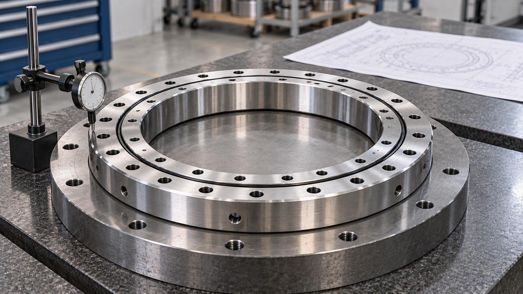
Review the assembly sequence while the drawing is open. Can the bearing be lowered into position without colliding with nearby parts? Can installers reach every fastener and apply the specified tightening method? Can seals and lubrication points be reached after the equipment is assembled? On a geared model, can the pinion mesh be checked and serviced safely?
Installation details should come from the instructions for the chosen bearing. Confirm the specified mounting-face condition, bolt procedure, initial lubrication, and the orientation of any marked soft zone or filling plug. Avoid copying a torque value or grease interval from a different model simply because the rings are similar in size.
For a replacement, examine the old part and the machine separately. Wear, damage, or past repairs can make measurements from a removed bearing misleading. Use the original identification and controlled drawing where available, then verify the current machine interface before ordering a substitute.
Send A Drawing Package That Answers The Key Questions
A useful inquiry includes the machine interface drawing, the proposed bearing position, the fixed and rotating sides, the drive layout, and the simultaneous load cases. Add the movement pattern, environment, service access, and any existing part identification. If you need the pinion, reducer, or other drive parts supplied, state that separately so the scope is clear.
Ask the supplier to return a model-specific drawing and to identify any assumptions that still need confirmation. Once both sides agree on the geometry, load cases, gear arrangement, and installation requirements, the choice of slewing ring bearings becomes a documented engineering decision rather than a visual match.
