
 SWBTEC


Slewing Drives: How To Choose A Practical Drive System
A rotating assembly needs more than enough torque to turn. It also needs to carry the forces acting through its mounting structure, move at the required pace, and stay controlled when the input power stops. That is why slewing drives should be selected as complete motion systems, not from an output torque figure alone.
The useful starting point is a short description of the job: what rotates, how often, how far, under which loads, and what must happen if motion is interrupted. Once those conditions are clear, a supplier can compare suitable drive arrangements against the same requirements.
What Is Included In A Slewing Drive?
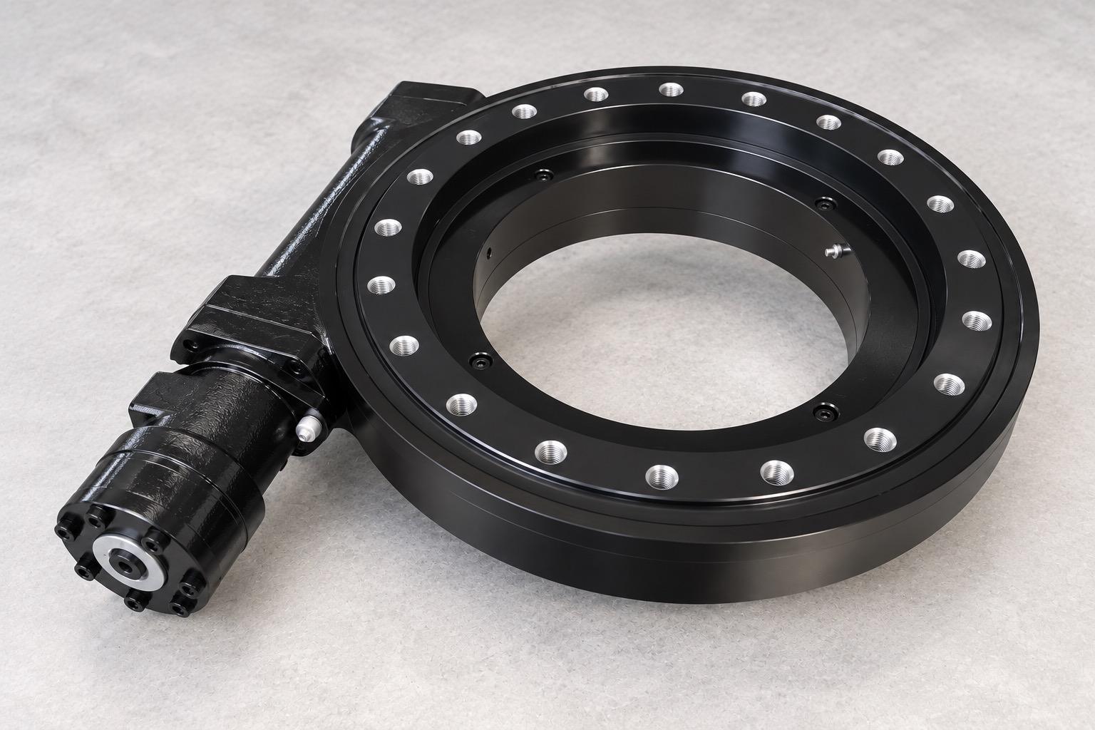
A slewing drive combines a slewing bearing with a torque-transmitting mechanism, a housing, and an input interface. A worm and wheel arrangement is one option; a pinion driving a ring gear is another. The bearing carries the structural loads while the transmission turns the output. A standalone slewing bearing provides support and rotation, but it does not by itself define the complete drive system.
The scope of supply matters. A quoted drive may be the mechanical assembly only. A motor, hydraulic input, additional reducer, brake, encoder, or other controls may be included separately or supplied by the equipment builder. Ask for an assembly drawing and a component list before comparing prices or planning the surrounding equipment.
Build The Load Case Before Comparing Torque
Record axial force, radial force, and overturning moment for each operating condition, including which forces occur together. Then add the output torque required during normal movement, starting, acceleration, reversal, and braking. The highest value in each column may come from a different event, so a list of unrelated maximums does not describe one real load case.
Movement changes the calculation. A drive that turns intermittently through a limited angle has a different duty pattern from one that rotates continuously. State the angle or speed, starts and stops, reversal frequency, running time, and rest time. For a positioning application, also define acceptable backlash and repeatability. A ratio alone tells you how input and output speeds relate; it does not establish accuracy or usable output torque.
Compare Worm And Pinion Arrangements On The Same Duty
A worm drive can offer a compact route to a high reduction ratio. Its efficiency, heat generation, duty cycle, and response to external torque still need checking for the actual operating conditions. A pinion arrangement may be a useful candidate where speed or efficiency has more weight, provided the gear mesh, input reduction, protection, and braking arrangement are addressed.
Do not assume that a worm drive will safely hold the load whenever power is removed. Backdriving behavior depends on the particular geometry, lubrication, wear, vibration, and external load. If holding position is a safety function, specify the maximum holding load and the loss-of-power state, then have the brake or other independent holding method verified.
Check The Interfaces That The Catalog Cannot See
The installation drawing should show the fixed and rotating sides, hole pattern, pilot features, central opening, housing position, and direction of the input shaft. Allow room for the motor or hydraulic connection, fasteners, tools, cable or hose routing, and future inspection. An apparently suitable ring diameter can still leave too little clearance for the housing or maintenance access.
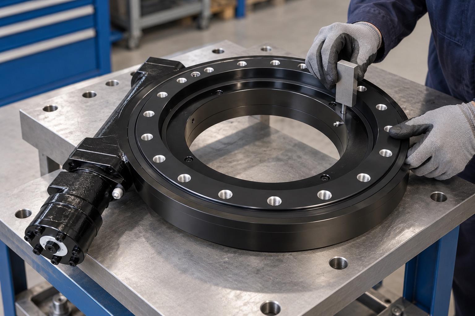
The supporting structure also matters. Confirm its stiffness and mounting surface condition against the chosen drive’s requirements; tightening bolts cannot correct a warped or flexible interface. Check the connection bolts and load path against the same operating cases used for the bearing and transmission. For a horizontal or inclined rotation axis, ask the supplier to confirm that the lubrication, seals, and load direction suit that mounting orientation.
Plan For The Environment And The First Inspection
Dust, water, corrosive exposure, temperature, and cleaning practices affect the housing, seals, and lubrication plan. A closed housing reduces direct exposure of the transmission, but its protection level and service needs are model-specific. Clarify which lubrication points serve the bearing, worm or gears, and input bearings; one visible port should not be assumed to cover every contact surface.
At commissioning, check rotation direction, smooth travel, unusual noise, leakage, temperature behavior, and brake or position feedback where fitted. The inspection plan should reflect the actual load, speed, temperature, contamination, and duty cycle. If performance changes during service, record whether the symptom appears at the transmission, bearing, input unit, or brake before adjusting components.
A Better Request For A Proposal
Send Slewbearingtec a duty table with simultaneous loads and motion cycles, the required torque and holding behavior, an interface drawing, installation orientation, environmental conditions, and the expected scope of supply. Ask for the controlled drawing and the basis used to check the bearing, gears, bolts, and thermal behavior. That gives the engineering review a concrete starting point and makes competing proposals easier to compare.
