
 SWBTEC


Slew Gear: Which Part Are You Ordering?
A machine can develop a knock at one point in its rotation, and the repair request may simply say “replace the slew gear.” That description is too broad for a reliable parts order. It might mean the large ring gear, the pinion that drives it, a gearbox, or a complete slewing drive. The first useful step is to identify the damaged part and the boundary of the replacement.
What A Slew Gear Can Mean
On a geared slewing bearing, teeth are cut into one of the bearing rings. A smaller pinion meshes with those teeth and transmits turning force from a motor and reducer. The bearing raceway carries the machine’s axial and radial loads and overturning moment. The gear pair transmits rotation. These are related functions, but they need separate checks.
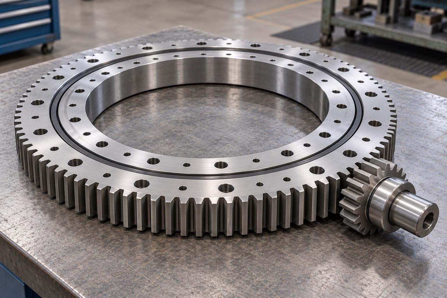
In some equipment, people use “slew gear” for the reducer or final drive rather than the teeth on the bearing. A parts list that says only “slew gear” therefore leaves too much open to interpretation. Ask for a drawing or clear photographs showing the mounting position, the teeth, and the neighboring components. Confirm whether the supply includes the bearing, ring gear, pinion, reducer, motor, or any combination of them.
Find The Teeth Before Choosing A Layout
An external-gear slewing bearing has teeth around the outside of a ring, with the pinion engaging from outside. An internal-gear bearing places the teeth along the inner circumference, so the pinion sits in the central opening. The two layouts have different space, guarding, and pinion-position requirements.
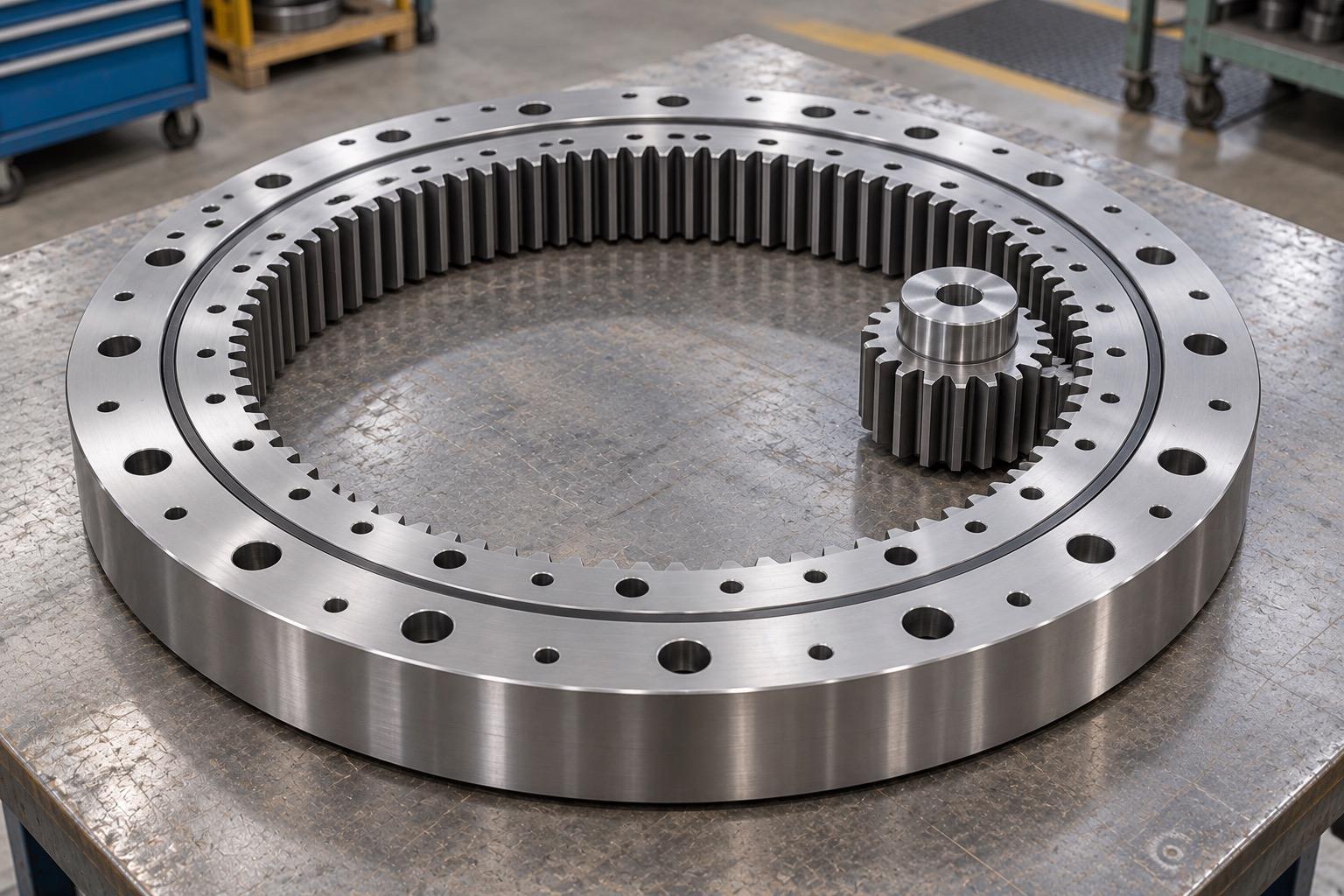
Slewbearingtec lists external-gear QW and internal-gear QN slewing bearing series, as well as gearless QU products. A gearless bearing still needs a separate way to rotate the equipment; its smooth ring is not evidence that the machine has no drive. When checking an existing assembly, identify which ring rotates and where the pinion shaft sits before selecting a replacement layout. The position of the teeth alone does not tell you which ring is fixed.
Why A Similar Diameter Is Not Enough
Two rings may fit the same general space yet have incompatible gear teeth or mounting interfaces. For a replacement, compare the controlled drawing with the existing assembly. Check the inner and outer diameters, height, locating features, mounting-hole pattern, tooth location, and pinion position. Then compare the gear data: module, tooth count, pressure angle, profile shift, face width, accuracy requirement, and any specified tooth-surface treatment. The mating pinion and center distance must also be accounted for.
The bearing and the gear need their own load checks. A bearing that meets the axial and overturning loads does not automatically have enough gear capacity for starting, braking, or reversing. Conversely, a suitable gear mesh does not prove that the bearing raceway or mounting bolts are suitable. If more than one pinion drives the ring, do not assume that the drives share load equally; synchronization, installation variation, and structural deflection can change the split.
Check The Mesh After Installation
The supporting structure affects the gear as well as the bearing. A distorted mounting surface can move the ring relative to the pinion and change the tooth contact. Gear adjustment should not be used to hide an unsuitable support surface.
Set and measure backlash at the positions specified by the manufacturer, then check it around the ring rather than at one convenient point. Record the measurement position, tool, and acceptance criterion. After adjusting the pinion, inspect the contact pattern across the tooth face. Edge contact can point to alignment or structural problems even when the gears turn freely by hand. Backlash that is too small can raise friction, heat, and tooth load; excessive backlash can increase impact, noise, and lost motion.
Lubrication is another separate check. Grease in the bearing raceway does not prove that the open gear teeth have been lubricated. The gear lubricant and its application plan should suit the load, speed, temperature, environment, and materials. The guard should keep debris and water away from the mesh while still allowing inspection and maintenance.
When The Problem Is Described As A Gear Failure
Record when the symptom occurs before ordering a part. A knock tied to a particular rotation angle may help locate a damaged tooth, a local raceway issue, or interference with nearby structure. Rising drive current, hydraulic pressure, or turning resistance can also come from the bearing, brake, reducer, or a distorted support. The symptom alone does not identify the failed component.
If a tooth has broken or the gear surface is badly damaged, inspect the mating pinion, shaft alignment, center distance, and possible impact loads. Replacing the pinion alone will not restore damaged ring teeth. Likewise, a new ring gear can suffer the same problem if the original mesh or support issue remains.
What To Send With A Parts Inquiry
Provide the original part number and machine identification if available, along with a drawing or measured mounting interfaces. Mark the fixed and rotating rings, internal or external tooth position, pinion location, and required supply scope. Include the gear geometry, duty and load information, and photographs of the wear or damage. These details let the supplier check the bearing, gear pair, and installation as a system—and help ensure that “slew gear” means the same part to everyone involved.
