 SWBTEC


Slew Drives: A Practical Guide To Worm Gear Units
A machine may need a turntable to move slowly while carrying a heavy, off-center load. In that situation, a motor and a reducer explain how torque reaches the rotating part, but they do not explain how the load is supported. Slew drives bring the bearing, transmission, housing, and mounting interfaces into one assembly. That makes them useful candidates for compact rotary mechanisms, provided the complete duty is checked rather than the drive torque alone.
Slewbearingtec includes worm gear slewing drives in its product range. The points below explain what this kind of unit does, where its limits arise, and what to put on a drawing or inquiry before choosing one.
What The Integrated Unit Actually Contains
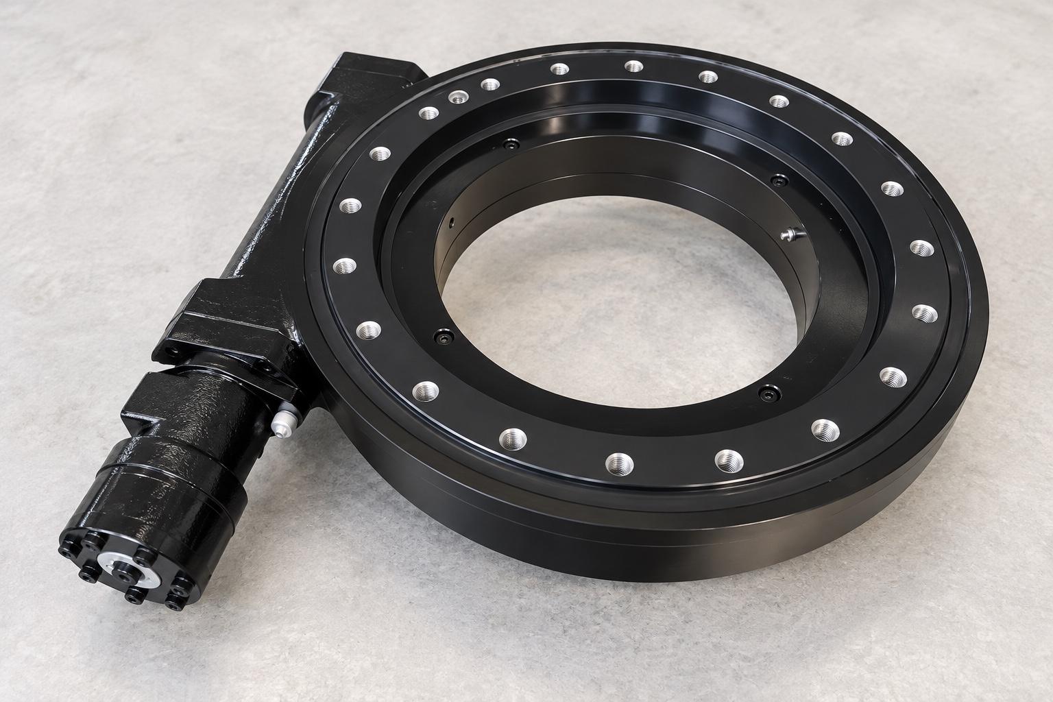
The slewing bearing is the load-carrying part of a slew drive. It connects the fixed and moving structures and accommodates axial force, radial force, and overturning moment. A worm engages teeth associated with a bearing ring to turn the output. The housing holds the transmission in position and provides a place for lubrication and seals.
This arrangement differs from buying a slewing bearing alone. A bearing may have gear teeth, but the equipment builder must still provide and align the driving pinion or other transmission, its input, and its protection. An integrated worm gear drive reduces that coordination work. It does not remove the need to design a stiff mounting structure or verify the connected machine.
The word “drive” also does not guarantee that a motor, gearbox, brake, encoder, or controls are included. Ask for an assembly drawing and supply list. Otherwise, two quotations that use the same product name may cover very different hardware.
Start With The Work The Output Must Perform
Describe the load at the rotating interface as a set of operating cases. For each case, record axial and radial force, overturning moment, output torque, and the direction of the forces. An off-center payload, acceleration, braking, or a change in machine attitude can alter the combination seen by the bearing. One “maximum load” figure is rarely enough to show which parts of the assembly are most heavily stressed.
Then describe movement. Is the mechanism making occasional positioning moves, swinging back and forth through a limited angle, or rotating for long periods? Give the travel angle, speed, starts and stops, reversals, operating time, and rest time. These details affect the bearing, worm mesh, lubrication, and heat balance. A unit that handles a short torque peak cannot automatically deliver the same output continuously.
Worm gearing can provide a large reduction in a compact space, which suits many slow rotary tasks. It also makes efficiency and temperature worth checking against the actual duty cycle. If the application needs sustained rotation or frequent reversals, request performance data for those conditions instead of judging the unit from a gear ratio or peak torque figure.
Holding A Position Is A Separate Requirement
Running torque turns the load. Holding torque concerns the external force acting when movement should stop. A third condition is reverse torque that may try to drive the mechanism backward. Put these requirements on separate lines in the specification, including what must happen after a power or control failure.
A worm gear should not be treated as a guaranteed safety lock. Lead angle, friction, lubrication, vibration, wear, and reverse loading all influence backdriving behavior. Where unwanted movement could create a hazard, define the allowable movement and check a suitable brake or mechanical holding measure as part of the machine design.
Make The Mounting Drawing Do Real Work
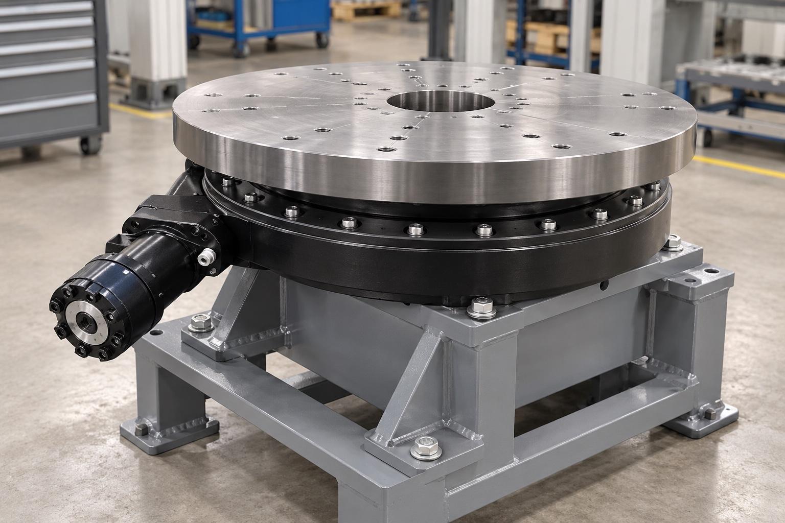
The drawing should identify which ring attaches to the fixed structure and which attaches to the moving part. Check bolt patterns, mating surfaces, available diameter, center opening, input orientation, and the space needed for any motor, hydraulic connection, hoses, cables, and service access. The axis may be vertical, horizontal, or inclined; orientation changes what must be checked for lubrication and sealing.
A compact housing cannot compensate for a flexible or uneven support. Distortion at the mounting interface can change how load enters the bearing and how the transmission runs. Review the base structure and bolted joints alongside the drive, especially where the output carries an offset load.
Plan For The Environment And Upkeep
An enclosure reduces direct exposure of the transmission, but it does not prove a particular protection level or make maintenance unnecessary. State the expected dust, water, temperature, corrosion, shock, vibration, and cleaning conditions. Confirm the seals, drainage, lubrication points, and inspection access for the selected unit.
During operation, changes in housing temperature, noise, vibration, leakage, input power, or backlash deserve investigation. Maintenance intervals should reflect load, speed, environment, and duty cycle rather than a generic schedule. The supplier's instructions should govern lubrication, inspection, and any internal adjustment.
What To Send With An Inquiry
A useful inquiry brings the pieces together: load cases, motion cycle, running and holding torque, reverse load, mounting orientation, interface drawing, environment, and required accessories. Ask the supplier to identify the exact assembly boundary and the conditions behind its ratings. For Slewbearingtec's worm gear slew drives, that is the practical way to move from a promising product category to a unit that can be checked against the real machine.
