
 SWBTEC


worm drive slew ring
SWBTEC supplies a worm gear slew drive that combines a slewing bearing, geared rotation, and a housing in one assembly. It supports a rotating structure while the worm input turns the ring at a reduced speed.
Send the loads, required output torque, motion cycle, and mounting drawing to discuss a configuration for your equipment.
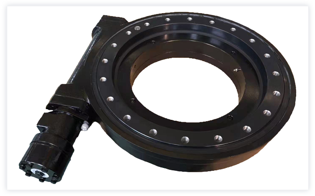
Worm Gear Slew Drive
Support and geared rotation in one assembly
The slewing bearing carries axial and radial forces and overturning moment between two structures. A worm meshes with the ring gear to turn the supported structure through a compact transmission path. The housing locates and protects that mesh.
This integrated arrangement reduces the separate bearing, pinion, and gearbox interfaces the machine builder would otherwise have to position. The drive input, mounting interfaces, sealing, and any required brake still need to match the machine design.
Select for combined load, torque, and duty
A useful selection starts with the loads that occur together at the slew axis. The bearing, gear mesh, mounting bolts, and input drive each have a different limiting condition, so a single maximum load or gear ratio cannot establish suitability.
| Design input | What it determines | What to provide |
|---|---|---|
| Combined loads | Bearing and bolt capacity | Axial force, radial force, and overturning moment for each operating and parked case |
| Drive demand | Worm, input drive, and gear sizing | Running, starting, peak, and holding torque with the required output speed |
| Motion cycle | Heat, wear, and lubrication demand | Rotation or swing angle, reversals, run time, and rest time |
| Position and hold | Backlash and stopping arrangement | Allowed movement, positioning accuracy, and the load to hold during power loss |
| Machine interface | Mounting and environmental configuration | Envelope, bolt patterns, input arrangement, installation orientation, and exposure |
Worm gearing may resist reverse rotation under some conditions. If uncontrolled movement could harm people or equipment, define a separate brake or locking requirement and verify the complete machine's stopping behavior.
Worm Gear Slew Drive
Review the offered assembly and share your drawing for a configuration matched to the actual load cases and installation space.
SWBTEC Worm Gear Slew Drive product image
Worm Gear Slew Drive
A bearing-supported worm drive for low-speed rotation in machinery. SWBTEC's published product configuration identifies a ductile-iron housing, steel bearing rings, and a ground steel worm; final dimensions and ratings depend on the selected design.
- Drive arrangementWorm gear with slewing bearing
- Published housing materialQT450-10 ductile iron
- Published worm material20CrMnTi steel
Fit the drive to the mounting structure
Check the available diameter, center opening, height, side input clearance, and both mounting bolt circles before choosing an outline. A stiff, flat support and correctly preloaded fasteners help the bearing distribute load as intended. The drive and rotating structure also need clearance through the full travel range.
For exposed equipment, specify temperature, dust, water, and corrosion conditions when requesting the seal, finish, and lubrication arrangement. Confirm the input device and flange or shaft interface in the same drawing set so the specified output speed and torque correspond to the installed motor or hydraulic drive.
Plan lubrication, inspection, and holding
Use the lubricant and service interval specified for the delivered assembly and its actual operating temperature and cycle. During service, inspect seals, fastener condition, abnormal noise, and changes in backlash or drive effort. Contamination and insufficient lubrication can damage both the bearing raceway and worm mesh.
Define the required stopped position and permissible movement for parked and power-loss conditions. A brake or mechanical lock must be selected against the governing external load when holding is a safety function; the presence of a worm gear alone does not establish that capacity.
Send the details for a drawing-based quote
Send a machine or replacement-part drawing with the bolt patterns, available envelope, rotating ring, and input connection. Add a load-case table with simultaneous axial force, radial force, overturning moment, torque, speed, and operating cycle. Include the environment, required holding behavior, quantity, and delivery destination.
SWBTEC can then discuss the drive configuration and confirm the drawing, rated conditions, supply boundary, price, and lead time for the specified order.
Send your drawing and load casesRequest a Worm Gear Slew Drive Quote
- Phone: +86 5634113031
- Email: [email protected]
- Address: Ningguo Dadao, Ningguo Economic Develope Zone, Ningguo,Xuancheng,Anhui,China
