

What Is The Torque Of A Slewing Bearing
The torque of the slewing bearing is the total rotational resistance that the drive system (such as your motor and pinion gear) must overcome in order to make the equipment rotate and maintain operation. She is not a single, fixed death value. It contains the sum of multiple resistances-both friction and the drag force brought by the seals. If it is a toothed support, there is also the resistance of the gear meshing.
In order to ensure that the drive selection does not go wrong, we usually use the following formula to calculate the total torque (M total ):
M total =M f +M s +M g
The logic here is clear:
M f= Friction torque under load (this is the load torque)
M s = friction torque generated by the seal
M g = friction torque generated by gear meshing (if toothed)
It is easy for engineers to confuse the difference between starting torque (pushing the device from rest to rotation) and running torque (maintaining rotation). The former is usually much larger than the latter. In addition, the preload inside the slewing bearing, the viscosity of the grease, the ambient temperature, and your specific working condition load will cause this value to fluctuate. Therefore, calculating this number is the first step to ensure the reliable operation of the equipment.
Let me break down these key parts.
Load-Carrying Torque (Mf)
It is the most important and complex part of the torque composition, which is directly derived from the external load applied to the bearing. Whether it is axial force, radial force, or overturning moment, will eventually be transmitted to the rolling body, causing friction in the raceway. The industry’s common estimation formula is this:
M f = ( F a * f a + F r * f r ) * μ * d m/ 2
Among them:
Fa = Axial load (N)
Fr = Radial load (N)
fa, fr = Calculation factors for axial and radial loads, specific to the bearing type (e.g., four-point contact ball, crossed roller), which are provided by the manufacturer.
μ (mu) = Coefficient of friction. This is an empirical value, typically ranging from 0.004 to 0.008 for clean, properly lubricated rolling bearings.
dm = Mean diameter of the raceway (pitch circle diameter) in meters (m).
Special reminder: If your application scenario is like a crane or excavator, there is a huge overturning moment, we usually convert this moment into “equivalent axial load” when calculating F a F a In order to calculate, so that the results are reliable.
Seal Friction Torque (Ms)
Most slewing bearings are equipped with rubber seals to lock grease and block dirt. These sealing strips slide close to the surface of the ferrule, and the resistance generated cannot be ignored. Interestingly, this part of the torque has little to do with the external load, but it has a great relationship with temperature and lubrication. Calculating it usually relies on empirical formulas:
Ms ≈ Cs * ds^2
Cs = A seal constant provided by the bearing manufacturer, which depends on the seal material and design.
ds = The diameter of the seal lip contact in meters (m).
In many engineering samples, you’ll find M s M s directly gives a reference value (N · m). What I want to emphasize is that for those bearings with small size and light load, the sealing torque is often the main source of no-load torque, and may even account for most of the total torque. Don’t ignore it when selecting the type.
Gearing Friction Torque (Mg)
For the toothed slewing ring, the meshing of the drive pinion and the large ring gear will also “eat” part of the force. This is related to the transmitted power and gear efficiency. Estimates are as follows:
Mg = Tdrive * (1 – ηg)
Tdrive = The driving torque transmitted through the gear teeth (N·m).
ηg (eta) = The efficiency of the gear mesh. For standard, well-lubricated spur or helical gears, efficiency is typically high, around 98% to 99% (i.e., ηg ≈ 0.98 – 0.99).
In other words, about 1-2% of the driving force will be lost in the gear friction, but this part is also the motor must overcome.
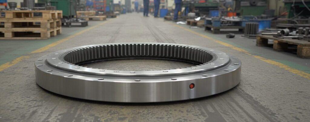
SLEWING BEARING
Rigorous Internal Quality Control、Expert Engineering & Innovative Design Capabilities、20 Years of Expertise in Slewing Bearing Manufacturing、Expert Engineering & Innovative Design Capabilities.
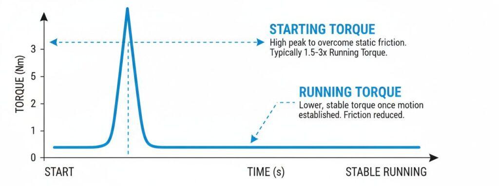
Starting Vs. Running Torque
To understand the difference between these two states is the key to the success of your motor selection.
Starting torque: This is the peak torque required to start rotation from a stationary state. It is high because you have to overcome static friction (the coefficient of static friction is much greater than the coefficient of dynamic friction), but also to overcome the “viscous” effect of seals and viscous grease (Stiction). The starting torque is usually 1.5 to 3 times the calculated running torque. Especially in a low temperature environment, or after the equipment is shut down for a long time, this multiple is even higher.
Running Torque: Once it moves, a stable oil film is established in the raceway, the friction is reduced, and the torque is stabilized. The above formulas mainly calculate the running torque.
When selecting a motor, it must be ensured that it can provide sufficient peak starting torque to “push” the equipment; and the continuous operation ability and heat dissipation performance of the motor are evaluated with reference to the operating torque. Ignoring this point is a common cause of the failure of the drive “small horse-drawn cart” and starting loading.
Key Factors Influencing Slewing Bearing Torque
In addition to the calculations on paper, there are several operational factors in the field that will actually change the total torque:
Internal preload: In order to increase the support rigidity, we often apply negative clearance (preload) during manufacturing. This directly increases the contact stress between the rolling element and the raceway, which inevitably leads to an increase in friction torque.
Lubrication condition: whether the oil is injected correctly and the viscosity is not suitable is very important. Insufficient lubrication or wrong viscosity will increase torque and accelerate wear.
Operating temperature: temperature fluctuations will change the grease viscosity. It is too cold, the fat thickens, and the starting torque soars; it is too hot, the fat becomes thinner, and the oil film may not hold up.
Installation accuracy: If the installation structure surface is not flat, or the rigidity is insufficient, the support will be forced to deform. This leads to local overloading of the raceway, generating abnormal friction and unpredictable “torque spikes”.
Author:David
With years of experience in mechanical engineering, I have witnessed firsthand how misunderstandings about torque can lead to system failures. I have written this guide to demystify slewing bearing torque calculations—from load and seal friction to the critical differences between starting and running torque. Hopefully, it will provide you with the practical knowledge needed to select the right drive system and ensure your equipment operates with the reliability and performance you expect.
