

What Is A Cross Roller Bearing
A Cross Roller Bearing is a high-precision rolling bearing where cylindrical rollers are arranged alternately at 90 degrees to each other between the inner and outer rings, specifically within a 90° V-groove raceway. The cylindrical rollers in a cross roller bearing establish line contact with the raceway surface. This unique geometry allows a single bearing to sustain heavy loads from all directions simultaneously—including radial, axial, and moment loads—while offering 3 to 4 times higher rigidity than conventional bearings. This means can replace a complex double-bearing arrangement with a single compact unit, significantly simplifying the rotational structure and maximizing space efficiency in high-precision applications like industrial robot joints, harmonic drives, and medical tomography equipment.
90 ° V-Groove Internal Geometry
The most typical feature of a cross roller bearing is actually written in its name: “Cross” arrangement. The cylindrical rollers are arranged in alternating positions at 90 degrees to each other. This is in contrast to standard bearing designs, which typically align rolling elements in a single parallel direction. Inside the 90 ° V-raceway, spacers or cages are usually installed between these crossed rollers. Don’t underestimate this internal structure, it plays a vital role: it prevents the rollers from tilting at high speeds and eliminates the friction that may arise from direct contact between the rollers. This precise geometric arrangement is the basis for the bearing’s ability to maintain high rotational accuracy.
Line Contact Vs. Point Contact
To truly understand the performance gap between crossed roller bearings and traditional angular contact ball bearings, we must look at the contact surface.
- Ball bearing (point contact): When the ball bearing is loaded, the contact area between the ball and the raceway is only a tiny point. Under heavy loads, this point creates a great concentration of pressure.
- Crossed roller bearings (line contact): As mentioned earlier, the cylindrical rollers are in line contact with the raceway surface. Since the load is distributed along a line instead of a single point, the elastic deformation under load is very small.
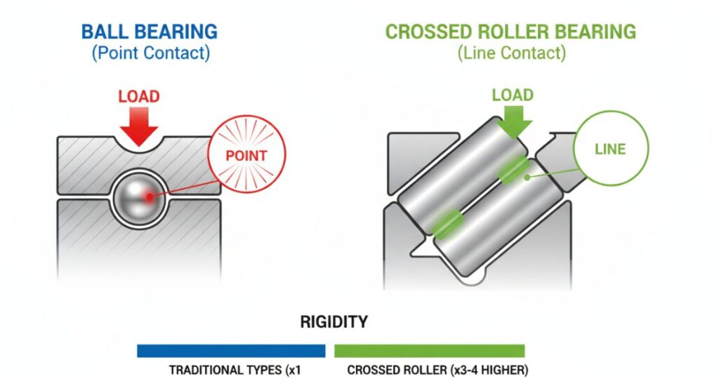
This physical principle explains why crossed roller bearings can provide 3 to 4 times higher rigidity than traditional types. For those application scenarios that require zero play and extremely high stiffness, this transition from point to line contact is often the decisive factor for success or failure.
Withstand Loads From All Directions Simultaneously
One of the most valuable capabilities of a crossed roller bearing is its ability to handle complex load combinations on its own. In traditional mechanical design, engineers often need to calculate the radial load perpendicular to the shaft and the axial load parallel to the shaft separately, which usually means that you need to configure different bearings for each force. However, thanks to this alternating 90-degree arrangement design:
- Half of the rollers are responsible for bearing the radial load;
- The other half of the roller is responsible for bearing the axial (thrust) load;
This combination gives the bearing excellent resistance to overturning moments (I. e. forces that cause tilting). This “all-in-one” load-bearing capacity eliminates the need for complex calculations of load directions, because it is designed to cope with heavy loads in all directions at the same time.
Replace Double Bearing Arrangement
By using crossed roller bearings, you can directly replace two bearings with one compact unit. The results are obvious:
- Reduced housing size: maximizing space efficiency, which is essential in compact machinery.
- Simplifies the rotating structure: fewer parts means fewer potential failure points and easier assembly.
High-Precision Application Areas
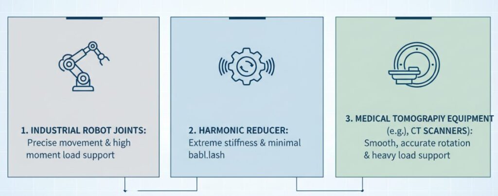
High rigidity, compact size and multi-directional load carrying capacity make crossed roller bearings the standard choice in certain high-end industries. Based on their unique characteristics, they are almost indispensable in the following areas:
- Industrial robot joints: The movement here must be precise, and the joint must support the weight of the arm when rotating (this is a typical moment load).
- Harmonic reducer: This type of precision reduction gear requires extremely high stiffness and minimal backlash.
- Medical tomography equipment: For example, CT scanners, the gantry must support huge weights in a compact frame while rotating smoothly and accurately.
Author:Jay
Hi, I’m a Senior Technical Engineer specializing in precision rolling bearings. With over 10 years of experience in the motion control industry, I focus on helping mechanical designers optimize rotational structures for robotics and automation by selecting the right high-rigidity bearing solutions.
