

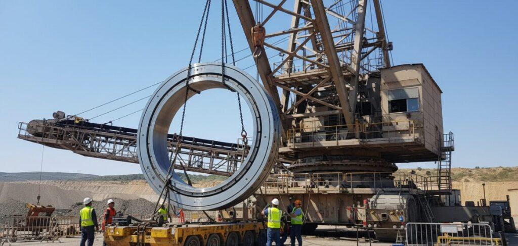
Stacker Reclaimer Slew Bearing Replacement
To completely complete the replacement of the slewing bearing of the stacker-reclaimer. The core of the whole project lies in the precise coordination of 3 links: a set of multi-point synchronous hydraulic jacking system capable of preventing structural distortion, extremely harsh flange flatness control (usually stuck within 0.15mm, which often depends on laser measurement and on-site processing), and a torque sequence agreement that cannot be touched by thunder during installation.
This is not only a change of parts, but also a comprehensive test of structural engineering calculation, heavy lifting technology and on-site precision measurement. We must ensure that the new bearing will not have “point load” or premature retirement of the raceway, so as to restore the performance of this big guy to the best state in the shortest downtime.
Here are the four key steps we must keep an eye on in practice:
Step 1: Structural Engineering Analysis And Center Of Gravity Calculation
Success or failure is actually determined by structural analysis before any tool is used.
Accurate calculation of the center of gravity (COG) is a prerequisite for life. Stacker reclaimer this kind of equipment, is inherently unbalanced load, all rely on a huge counterweight to balance the cantilever. When replacing the bearing, we need to separate the upper structure from the base. If the center of gravity data is inaccurate at this time, the machine will face the risk of overturning in minutes.
In the analysis phase, we focus on these points:
- Load distribution: The weight of the cantilever, counterweight and central structure must be perfectly balanced.
- Variable load: The weight of materials (such as accumulated coal and ore powder) and auxiliary equipment remaining on the machine must be taken into account. These “invisible weights” will make the calculation results deviate.
- Jack layout: the analysis report must clearly indicate the specific landing point of the hydraulic jack. If the position is a little off, it may lead to excessive stress in the structural parts and even crush the structure.
Step 2: Multi-Point Synchronous Hydraulic Jacking
Lifting up the superstructure is the most visually stunning, but also the most frighteningly scary, step in the entire replacement process. A synchronous multi-point hydraulic jacking system must be used here.
Why must the emphasis be on “synchronization”?
- Prevent structural distortion: Although this large steel structure looks hard, it is actually very afraid of being biased by “strength. If one side is lifted faster than the other, the rigid structure will twist. In my experience, this torsion often leads to permanent deformation of the frame, which is catastrophic.
- PLC precision control: now do this kind of project, rely on the human eye pressure gauge has long failed, must be on the PLC control system. It can monitor the pressure and displacement of each jack in real time to ensure that the entire superstructure rises evenly like on a horizontal plane, and the error is controlled at the millimeter level.
- Safety lock nut: after the jacking is in place, the mechanical locking ring must be locked immediately following the jack stroke. This is the last line of defense for lifting teams operating under suspended loads.
Single Row Ball Slewing Bearing
Single-row ball slewing bearings are divided into internal tooth, external tooth and toothless structure, which are suitable for a variety of transmission needs.
Double Row Ball Slewing Bearing
Double-row ball slewing bearings are specially designed for super-heavy load scenarios.
Slewing Bearing With External Gear
The external gear internal flange slewing bearing integrates the advantages of external gear transmission and internal flange mounting.
Slewing Bearing With Internal Gear
The internal tooth and external flange slewing bearing is characterized by the combination of internal tooth transmission.
Slewing Bearing Without Gear
Gearless double flange slewing bearing is light weight and compact.
Cross Roller Slewing Bearing
Single-row cross roller slewing bearing adopts roller cross layout, large contact area, can synchronously and efficiently withstand axial and radial loads and overturning moment,
Step 3: Flange Flatness Verification And On-Site Processing
Industry standards typically require a flatness error of less than 0.15mm.
- Laser measurement: in the face of stacker reclaimer this size of equipment, the traditional manual measurement is simply child’s play. We now use a laser tracker to scan the entire mounting flange surface and directly generate a 3D topographic map of the base.
- On-site processing: Nine times out of ten, the flange face of old equipment is warped, pitted or out of tolerance. If a new bearing is installed directly on this surface, a “point load” will occur “. This will lead to uneven bearing raceway force, it will not be long will be bad.
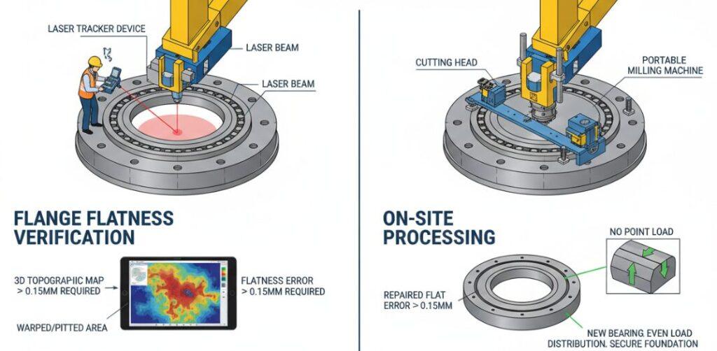
In this case, the portable processing equipment must be directly mounted on the machine and the flange surface must be milled or ground until it is repaired to within the flatness requirement of 0.15mm. Only when the foundation is well laid can the bearing sit firmly.
Step 4: Installation And Calibration Torque Sequence
To the last step-the installation of new components and fastening. Tightening bolts is not as simple as tightening them, and the calibrated torque sequence protocol must be strictly adhered.
- Torque sequence: The bolts must be tightened in a specific pattern (usually a star/diagonal pattern) in order to spread the clamping force evenly. If you twist one by one along the circle, the bearing will deform like a wave, which directly leads to an increase in internal friction.
- Fasten in stages: Protocols usually require tightening in stages, such as first to 30% of the final torque, then to 60%, and finally to 99% or 100. This allows the bearing to “sit” a little bit.
- Final verification: A calibrated hydraulic torque wrench or bolt tensioner must be used to ensure that the preload of each bolts is fully in accordance with the OEM (original manufacturer) specifications.
Author: David Stone
As a Senior Mechanical Engineer specializing in heavy industrial assets, I focus on the structural analysis, multi-point jacking systems, and on-site metrology required for precise stacker reclaimer slew bearing replacements.
