

Slew Bearing Replacement Procedure
The replacement of slewing bearing must strictly follow a set of six-stage standard process: from safety preparation, systematic disassembly, installation surface inspection, to “soft belt (Soft Spot)” alignment installation, grading bolt tensioning, and finally lubrication running-in.
This video provides an overview of the excavator slew bearing replacement process:
The specific implementation process is as follows:
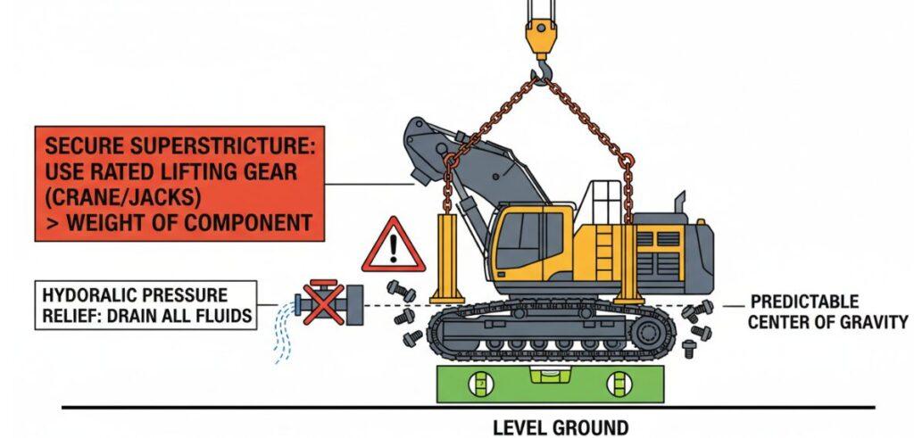
- The first is safety and site preparation, to stop the equipment on the ground at an absolute level, release all hydraulic pressure, and use reliable lifting equipment to fix the upper structure to prevent rollover.
- The second is disassembly. Before disassembling the upper bolt and the old support, the hydraulic pipeline must be clearly marked.
- The third step is also the most critical installation surface inspection. A laser level or feeler gauge must be used to ensure that the flatness is within the OEM tolerance (usually less than 0.15mm), as uneven surfaces can cause the raceway to deform immediately.
- The fourth step is the installation of the new bearing. The “S-shaped gap” or “soft belt” (induction hardened joint) must be placed in the minimum load zone (zero stress zone) to prevent premature cracking.
- The fifth step is to tighten the bolt, using a calibrated hydraulic torque wrench, in a criss-cross pattern (star sequence) in 3 stages -30, 80 and 100 percent of the final torque-to ensure uniform preload.
- Finally, lubrication and running-in, inject new lithium-based EP2 grease, and rotate the equipment to verify whether the operation is stable, and check whether the axial clearance is stable.
The following is a detailed technical dismantling of each stage:
Step1: Safety And Site Preparation
Before any tool touches the equipment, it must be ensured that the equipment is parked on an absolutely level ground. This is not only to facilitate the work, but also to ensure that when the upper structure is taken apart, the center of gravity is predictable.
At this stage, there are two safety measures that must be closely watched:
- Hydraulic pressure relief: All hydraulic pressure in the system must be completely drained . Too many cases of accidental movement of components or injury caused by hydraulic oil spray during disassembly due to residual pressure in the pipeline.
- Fixing the superstructure: Proven lifting equipment must be used-whether a crane or a jack, with a load rating significantly higher than the weight of the superstructure. Our goal is to hold the car firmly and prevent the superstructure from overturning or shifting catastrophically once the connecting bolts are removed.
Step2: Systematic Dismantling
The efficiency of reassembly actually depends on the accuracy of disassembly. These stages need to methodically deal with the complex network of connections between the chassis and the car.
- Hydraulic Line Marking: Before unscrewing any bolts, systematically label and seal each hydraulic and electrical connection through the slewing bearing. This is not only to prevent dust, but also to ensure that you don’t connect the wrong wire when you put it back
- Removal sequence: Once the superstructure is safely supported and all piping is disconnected, the mounting bolts can be removed. Then carefully remove the old bearing. This is usually a dirty job, but in the process of pulling out the old parts, extreme care must be taken not to let debris fall into the gearbox or mounting holes.
Step3: Installation Surface Inspection
The mounting interface must be as clean as a surgical table and the structure must be intact.
- Check flatness: The technician must use a laser level or a high-precision feeler gauge to map the flatness of the mounting frame.
- OEM tolerance: surface flatness must usually be controlled within the tolerance range of <0.15mm. If this deviation is exceeded, the mounting surface will become a “fulcrum”, twisting the new bearing when tightening the bolt. This leads to immediate deformation of the raceway, tight spots when rotating, followed by rapid fatigue failure. Any burrs, old sealant or rust must be thoroughly removed and the bare metal must be exposed.
Single Row Ball Slewing Bearing
Single-row ball slewing bearings are divided into internal tooth, external tooth and toothless structure, which are suitable for a variety of transmission needs.
Double Row Ball Slewing Bearing
Double-row ball slewing bearings are specially designed for super-heavy load scenarios.
Slewing Bearing With External Gear
The external gear internal flange slewing bearing integrates the advantages of external gear transmission and internal flange mounting.
Slewing Bearing With Internal Gear
The internal tooth and external flange slewing bearing is characterized by the combination of internal tooth transmission.
Slewing Bearing Without Gear
Gearless double flange slewing bearing is light weight and compact.
Cross Roller Slewing Bearing
Single-row cross roller slewing bearing adopts roller cross layout, large contact area, can synchronously and efficiently withstand axial and radial loads and overturning moment,
Step4: Soft Belt Alignment Installation
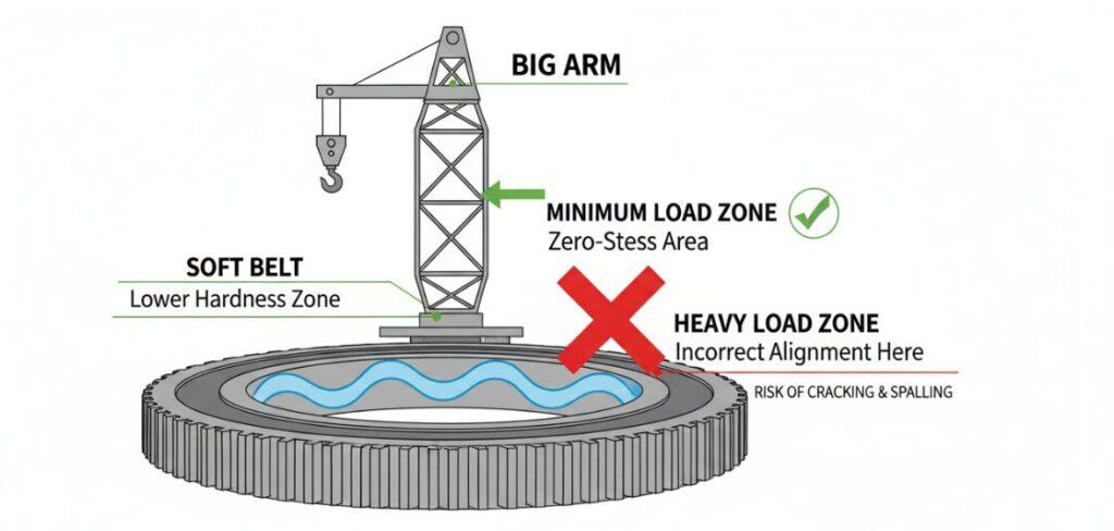
In the new bearing installation stage, the direction of the ring body is definitely not casually placed. Each slewing bearing has an “S-shaped gap” or “soft belt”. This mark represents an induction hardened joint on the raceway, where the hardness is locally lower compared to the rest of the ring body.
- Zero-Stress Zone: The program enforces that this soft band be placed strictly in the minimum load zone (often referred to as the zero-stress zone).
- Why alignment is important: if the soft belt is placed in a heavy load area (such as directly under the big arm when lifting operations), it is equivalent to exposing the most vulnerable part of the ring to the greatest stress. Correct alignment is the fundamental guarantee to prevent premature cracking and raceway spalling.
Step5: Graded Bolt Tensioning
Screwing bolts is a scientific process, not a greater strength than anyone else. To ensure that the bearing fits flat on the mounting surface without warping, a calibrated hydraulic torque wrench must be used.
The tightening process must strictly follow a criss-cross pattern and be carried out in 3 progressive stages:
- 30% of the final torque: This is times to allow the bearing to seat and ensure that the threads are properly engaged.
- 80% of final torque: These stages provide the main clamping force and allow the assembly to set.
- 100% of final torque: The specified preload is reached in the last pass.
If you directly on a bolt full torque, and then go to unscrew a, will be the ring body “pinch”, resulting in permanent deformation. The star pattern ensures that the load is evenly distributed across the diameter.
Step6: Lubrication And Running-In
The final step in the replacement procedure is to ensure that the component is in service condition. The bearing must be purged with fresh grease to form a hydrodynamic film between the rolling elements and the raceways.
- Grease specifications: Lithium-based EP2 (extreme pressure) grease is usually required, but it is best to check the specific specifications of the OEM.
- Verification of running-in: inject grease while rotating the equipment slowly. This rotation has two purposes: the 1 is to distribute the grease evenly, and the 2 is to allow the technician to verify that the operation is smooth.
- Axial clearance check: Finally, don’t forget to use a dial indicator to check whether the axial clearance is stable, and confirm that the bearing is installed correctly and there is no accidental shaking under load.
Author: Mark Reynolds
“I am a Senior Heavy Equipment Engineer with over 15 years of field experience. Specializing in slewing drive systems, I authored this guide to standardize the slew bearing replacement procedure. My focus is on critical precision details—from verifying mounting surface flatness to <0.15mm with laser levels, to ensuring the ‘soft spot’ is correctly positioned in the zero-stress zone. “
