

How Do I Choose A Slewing Bearing
To choose the correct slewing bearing, you must primarily determine the three critical load parameters: Axial Load (Fa), Radial Load (Fr), and the Tilting Moment (M) generated by the equipment’s counterweights and payload. Specifically, you need to calculate these loads under the equipment’s maximum working conditions and apply a suitable Safety Factor (typically 1.10 to 1.67 depending on the application) to ensure the bearing’s raceway and bolting connection will not fail. Once the factored loads are calculated, you must overlay these data points onto the manufacturer’s Static Limit Load Curves. The intersection point of your resultant load must fall below the limit curve of the selected bearing type (such as a Single-row Ball for general applications or a Three-row Roller for heavy-duty loads) to ensure structural integrity and operational longevity.
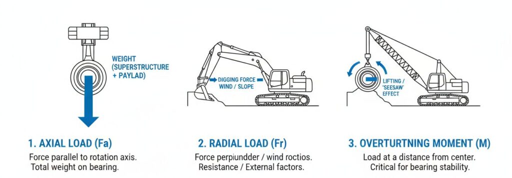
Identify The 3 Key Load Parameters
Axial load ( F a ): This is the force parallel to the rotation axis. In most vertical axis applications (such as cranes or excavators), this is actually the total weight of the superstructure plus the payload, which is actually pressing on the bearings.
Radial load ( F r ): This is the force perpendicular to the rotation axis. It usually comes from the resistance of the work (such as digging force), or external factors, such as wind load or slope force generated by slope work.
Overturning moment ( M ): This is often the most critical and most problematic parameter in the selection of slewing bearings. The moment is generated by the load acting at a certain distance from the center of the bearing. Simply put, the payload and counterweight create a “seesaw” effect that attempts to “lift” the bearing from the mounting structure.
Calculation Of Load Based On “Maximum Operating Conditions”
Many novices in the answer “how to choose”, a common mistake is to use only rated load or static load. To ensure safety, you must calculate the load of the equipment under maximum operating conditions. This means that you must consider the “worst case” that the device may face, including:
- Maximum payload capacity.
- Dynamic forces resulting from a sudden stop or sudden acceleration.
- The wind pressure on the towering structure.
Using the maximum operating condition data ensures that your calculation inputs represent the highest stresses that the bearing can encounter over its entire service life.
Add The Correct Safety Factor
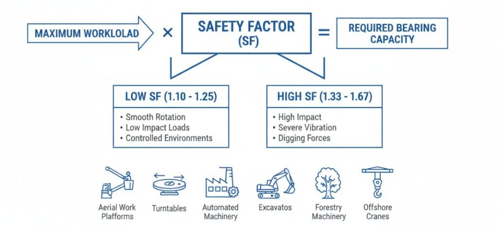
Once the maximum workload is determined, it must be multiplied by a specific safety factor. This factor acts as a buffer to account for shock loads, unknowns in operation, and criticality of the application. The safety factor is usually between 1.10 and 1.67:
- Low range (~ 1.10 – 1.25): Suitable for applications with smooth rotation, low impact loads and controlled environments (such as aerial work platforms or turntables).
- High range (~ 1.33 – 1.67): Essential for heavy-duty applications involving high impact, severe vibration or digging forces, such as excavators, forestry machinery or offshore cranes.
This factor is added to ensure that even under unexpected stress peaks, the bearing’s raceway and bolted connections are strong enough not to fail.
Analysis Of Static Limit Load Curves
The use of the manufacturer’s static limit load curve. These charts are a visual representation of the bearing capacity. You need to plot the calculated load (axial load and overturning moment) with a safety factor on these charts.
- Intersection: Find the moment you calculated on the graph ( M ) and axial load ( F a ) of the meeting point.
- Safe area: a suitable bearing, the intersection point of which must fall below the limit curve.
If the point falls above the curve, it means that the bearing is small and you are facing the risk of raceway deformation or bolt fracture. If the point falls far below the curve, it means that the bearing is technically competent.
Select The Bearing Type According To The Load Strength
Finally, the position of your load point on the curve will determine the specific bearing type.
- Single-row slewing bearings: If your calculated intersection falls below the limit curve of a standard single-row ball bearing, this is usually the most cost-effective option for medium-load general-purpose applications.
- Three-row column slewing bearings: If your load is extremely high, especially the radial load or overturning moment is huge, which exceeds the bearing capacity of the ball bearing, then you must upgrade to a three-row column design.
Author:Danniel
“I am a Senior Application Engineer specializing in slewing bearing technology. With over a decade of experience in heavy machinery design, I help engineers navigate complex load calculations—from Axial and Radial loads to Tilting Moments. My expertise lies in analyzing static limit load curves to ensure precise bearing selection for safety and longevity.”
