
 SWBTEC


What Is A Slewing Bearing? Slewing Ring Applications
A slewing bearing is a highly specialized, large-diameter rolling-element bearing designed to simultaneously support heavy axial forces, radial loads, and significant tilting moments within a single integrated unit. These components physically connect a machine’s stationary base to its rotating superstructure, incorporating bolt holes for direct mounting and often featuring integrated gear teeth for drive mechanisms. Defining the component is simple; ensuring it survives the physical demands of a 500-ton crane or an offshore wind turbine is highly complex. Field data shows that 70% of premature slewing ring failures stem not from incorrect static load calculations, but from dynamic oscillatory wear profiles that designers completely overlook during the initial drafting phase. We need to dissect the exact mechanical frameworks that separate successful heavy machinery designs from catastrophic field failures.
The C.A.R.T. Selection Framework
Engineers dictate the mechanical viability of a slewing bearing by evaluating four interlocking metrics through the C.A.R.T. framework. Most supplier catalogs only highlight basic static capacity, leading designers to under-spec components for complex environmental stresses. Evaluating all four vectors ensures the bearing geometry matches the exact field application.
Capacity
Thrust and tilting moments act on slewing rings simultaneously, requiring specific internal contact angles. Single-row four-point contact ball bearings handle generalized loads, but designers specify triple-row cylindrical roller bearings when structural tilting moments exceed standard deflection limits.
Arc
The operational swing path determines the internal raceway degradation rate. A 360-degree continuous rotation distributes friction and lubricant evenly. A limited 45-degree oscillation path causes localized stress fatigue on a small cluster of rolling elements.
Rigidity
Slewing rings offer zero inherent stiffness if the mounting substructure warps under load. Machined flatness on the mating surface prevents the bearing from distorting into an oval shape during heavy lifting operations.
Torque
Internal preload levels directly dictate the starting torque required to move the superstructure. Designers specify negative clearance to eliminate play in precision robotics, accepting the trade-off of higher friction and higher torque requirements from the slewing drive.
C.A.R.T. Metrics Comparison Table
| Metric | Single-row Ball (Four-Point Contact) | Crossed Roller | Triple-row Roller |
| C – Capacity | |||
| Axial Load Capacity | Moderate | High | Very High (Highest) |
| Radial Load Capacity | Moderate | High | Very High (Highest) |
| Moment Load Capacity | Moderate | High | Exceptionally High |
| Envelope Efficiency | High (Good capacity for its size) | Very High (High capacity in compact space) | Moderate (Requires larger envelope) |
| A – Accuracy | |||
| Rotational Accuracy (Runout) | Moderate | High to Very High | Moderate to High |
| Backlash / Play | Standard clearance; difficult to preload heavily | Can be preloaded for zero clearance / backlash | Generally has slight clearance; less ideal for high-precision positioning |
| R – Rigidity | |||
| Radial/Axial Stiffness | Moderate (Point contact leads to more deflection) | High (Line contact increases stiffness) | Very High (Multiple roller rows minimize deflection) |
| Moment Rigidity | Moderate | High | Exceptionally High |
| T – Torque | |||
| Frictional Torque | Low and relatively consistent | Moderate to High (Increases with preload) | High (Due to multiple rollers and seals) |
| Torque Sensitivity to Mounting | Low to Moderate (More forgiving of structure flatness) | High (Requires very flat mounting surfaces to avoid binding) | Moderate to High |
High-End Slewing Ring Applications By Industry
Equipment manufacturers deploy different internal bearing architectures depending on the precise mechanical demands of the target industry. The application dictates whether the internal raceway utilizes balls, crossed rollers, or distinct load-separating roller rows.
Wind Energy: Yaw And Pitch Systems
Wind turbine blade pitch control generates continuous micro-movements that rapidly degrade standard bearing raceways. Yaw slewing bearings at the top of the tower must endure massive wind shear and the extreme over-turning moment of the nacelle. Engineers specifically deploy double-row ball bearings or heavily sealed cylindrical roller variants here to withstand unpredictable offshore weather dynamics.
Heavy Construction: Excavators And Tower Cranes
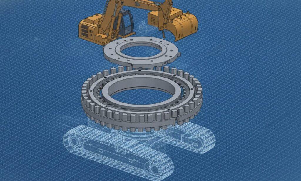
Excavators rely heavily on slewing rings with integrated internal gear teeth to protect the drive pinion from environmental debris. The massive counterweight and the extended boom create extreme teeter-totter physics. Triple-row roller slewing bearings separate the thrust, radial, and tilting forces into three distinct raceways, ensuring the excavator base remains stable while lifting heavy payloads at full reach.
Precision Robotics And Medical Equipment
Surgical imaging machines require near-zero rotational runout and whisper-quiet operation. Designers specify crossed roller slewing bearings for these precise applications. The alternating 90-degree cylindrical rollers handle high-moment loads within an extremely compact cross-sectional profile, allowing the medical equipment to remain lightweight and highly accurate.
The “False Brinelling” Oscillation Trap
Lubrication starvation in short-arc oscillating applications remains the number one cause of premature slewing bearing failure in heavy equipment.
Designers mistakenly schedule maintenance intervals based on continuous 360-degree rotation assumptions. A continuous rotation drags the bearing grease through the entire load zone, keeping rolling elements protected. Cranes and material handlers frequently swing back and forth across a tight 60-degree arc. This highly repetitive, heavy-load micro-movement physically squeezes the lubricating grease out of the raceway contact patch. The rolling elements eventually grind against dry steel, creating deep indentations known as false brinelling.
Engineers fix this by specifying automated, multi-point progressive lubrication systems that physically force fresh grease into the specific quadrant of the bearing enduring the heaviest tilting moment during operation.
The Latest Trend: Smart Slewing Rings With IIoT Integration
The offshore heavy lifting industry completely abandoned manual inspection protocols in favor of integrated sensor arrays directly machined into the bearing rings.
Replacing a damaged slewing bearing on an offshore platform costs tens of millions of dollars in downtime and specialized crane vessel rentals. Modern manufacturers now embed strain gauges and vibration sensors inside the stationary ring of the bearing. These Industrial Internet of Things systems transmit real-time telemetry regarding micro-fractures, raceway deflection, and internal friction spikes. Equipment operators use this data feed to predict exactly when a bearing will fail, allowing them to schedule replacement operations months in advance during favorable weather windows.
FAQs
What is the difference between a slewing bearing and a slewing drive?
A slewing bearing is the structural rotating joint itself. A slewing drive is a complete, enclosed system that houses a slewing bearing combined with a dedicated worm gear or pinion motor to actively power the rotation.
How do you properly lubricate a slewing ring?
Maintenance teams must slowly rotate the bearing while actively pumping extreme-pressure lithium-based grease into the zerk fittings. This ensures the rolling elements carry the fresh grease evenly across the entire internal raceway.
Can a slewing bearing rotate at high speeds?
Standard slewing rings operate strictly in low-speed, high-load environments. Applications requiring high-speed rotation demand completely different bearing topologies focused on heat dissipation rather than heavy tilting moment capacity.
Why do slewing bearings have gear teeth?
Integrated gear teeth eliminate the need for secondary external transmission systems. Engineers bolt a hydraulic or electric drive pinion directly against the bearing’s gear, drastically reducing the physical footprint of the machinery’s rotation mechanism.
How do you measure slewing bearing wear?
Technicians measure internal raceway wear by conducting a “tilt clearance test.” They position a dial indicator against the bearing face, apply a maximum safe load to the machine boom, and measure the physical vertical separation between the inner and outer rings.
