To perform a proper crane slew bearing rocking test, you must measure the axial displacement of the bearing under opposing load moments. First, position the crane boom to create a maximum forward moment and zero your magnetic dial indicator, placing the probe between the rotating superstructure and the fixed undercarriage race. Next, reverse the moment (typically by hoisting a heavy load or booming up to a minimum radius) to “rock” the bearing backward. Record the total deflection shown on the dial. Compare this value against the manufacturer’s “Max Allowable Wear” chart; generally, a deflection exceeding 2.0mm to 3.0mm (depending on ball diameter and crane model) indicates structural fatigue and requires immediate bearing replacement to prevent catastrophic failure.
Understand The Physical Logic Behind Swing Testing
The fundamental purpose of this test is to quantify the degree of wear within the bearing raceways and rolling elements. We do this by measuring the axial displacement.
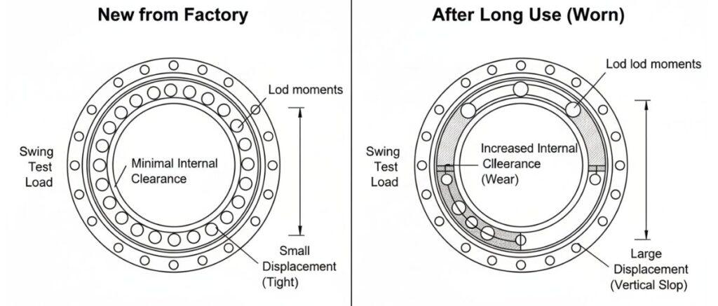
When new bearings leave the factory, the internal clearance is very small. However, after working on the construction site for a long time, the ball or roller will continuously grind on the raceway, and the gap will naturally become larger. To put it bluntly, the swing test is to use the two opposite load moments before and after the to forcibly “push” the bearing from one extreme position to the other. This physical displacement directly exposes how much vertical “slop” is generated inside the entire component.
Necessary Tools For Work
According to the process, accuracy is the bottom line. The guy who eats is mainly a magnetic base dial indicator.
Placement: The base must be firmly sucked on the chassis (or other fixed parts) and must not shake. The probe must cross the gap and top the rotating upper structure.
Zero: It is very important to zero the table at the maximum forward tilt moment. If the table is not returned to zero before the load is reversed, the last read data is nonsense, misdiagnosing the bearing health condition but going to be a big deal.
Stepwise Disassembly Of The Measurement Process
Step 1: Make The Maximum Forward Tilting Moment
The first step in the test is to shift the center of gravity. Put the big arm forward (usually lie down to the large radius under no load, or with a little light load, depending on the instructions of the car), and use the weight of the big arm to force the car structure to “plant” forward “. This will cause the front end of the bearing to be compressed and the rear end to be tilted.
Note: This is the best time for you to install and zero the dial indicator at the rear of the bearing.
Single Row Ball Slewing Bearing
Single-row ball slewing bearings are divided into internal tooth, external tooth and toothless structure, which are suitable for a variety of transmission needs.
Single-row cross roller slewing bearing adopts roller cross layout, large contact area, can synchronously and efficiently withstand axial and radial loads and overturning moment,
If the benchmark is good, the load dynamics must be completely reversed. To measure total wear, you have to change the car from a “forward trend” to a “backward trend”.
Lifting heavy objects: As mentioned earlier, lift a calibrated test counterweight, which will pull the big arm down and use the lever principle to pry the car’s bottom up.
Variable luffing: Or, directly lie down the big arm to the minimum radius (high elevation angle) and move the center of gravity back.
This conversion process will make the bearing “swing”. As the balance changes, you will see the physical lift of the upper structure at the rear (where you put the watch).
Interpreting Deflection Data
I got the reading on the table, and the most test of experience was just beginning.
Maximum Allowable Wear Chart
Don’t expect a universal “pass line” to apply to all cranes. You’ll have to look up the manufacturer’s chart for that particular machine of yours. This table takes into account too many variables: the specific crane model, the diameter of the ball or roller, and the clearance value of the original design.
Hazardous Area: 2.0mm To 3.0mm
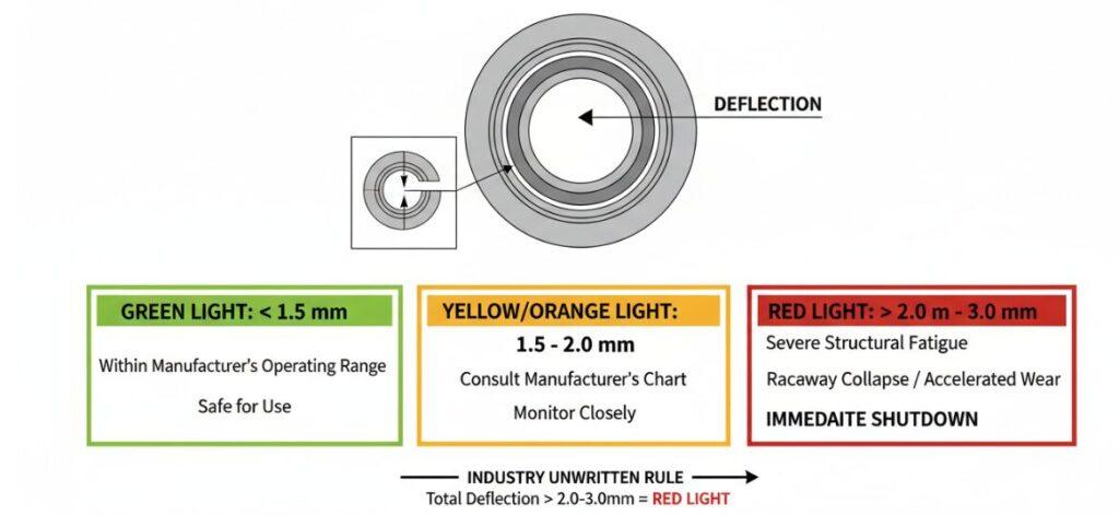
Although the specifications are different, there is an unwritten rule in the industry: if the total deflection exceeds 2.0mm to 3.0mm, it is a red light.
<1.5mm: usually within the operating range allowed by the manufacturer, it can be used.
2.0 mm-3.0mm: This level of displacement means severe structural fatigue. At this time, the surface hardening layer of the raceway is estimated to have collapsed, and the wear speed will be exponentially accelerated.
Why Replace Now?
If your swing test results exceed the standard, there is only one action plan: change the bearing immediately, there is no discussion.
In this business, ignoring the gap of more than 3.0mm is a gamble. For cranes, failure refers not to downtime, but to “turn off the turntable”-the direct separation of the rotating car and the chassis. Rigorous implementation of this test process-measuring displacement under opposite moments-is your only line of defense for the structural integrity of your equipment and the safety of your worksite.
Author:David Miller
I’m a Heavy Equipment Inspection Specialist with over 15 years of field experience. I focus on crane structural integrity, specializing in slew bearing rocking tests and wear analysis. I hope to help operators accurately measure axial displacement and interpret diagnostic data to prevent catastrophic equipment failures.
Please enter your email address, and our customer service team will contact you shortly to confirm the shipping details. We’ll be happy to send you a free sample along with the material certificates (MSDS/COA) at no cost.
Send Us a Message
Please fill in your email address, and our manager will contact you to confirm your mailing address and mail you samples and material certificates (MSDS/COA) free of charge.