

Slewing Bearing Wear Measurement
To accurately measure slewing bearing wear, the most effective method is the “Tilt Clearance Measurement”. This process involves measuring the axial movement of the bearing under load reversal. First, secure a magnetic dial indicator to the non-rotating structure, positioning the probe tip on a clean surface of the rotating raceway (typically the bearing’s nose). Zero the indicator under a static load, then apply a reverse moment load (using the equipment’s boom or hydraulics) to tilt the bearing. Record the total deflection at four equidistant points (0°, 90°, 180°, and 270°). If the measured increase in clearance exceeds the manufacturer’s specified wear allowance (typically 1.5mm to 3.0mm depending on the bearing diameter), the bearing has reached its service limit and requires immediate replacement to prevent structural failure.
Understanding Overturn Clearance Measurement
The principle of the above set of operations is to capture the internal geometric changes caused by raceway wear. When dealing with “slewing bearing wear measurement”, we are staring at the ever-increasing axial gap. The raceway wears slowly because of friction and heavy load, and the gap between the rolling body and the raceway naturally becomes larger.
Why is the “swing test” the industry standard? Because it simulates the dynamic force of the machine when it is working. It is completely different from that kind of static inspection. This method uses the weight of the machine and hydraulic power to abruptly “shake” the car relative to the car, so as to force out the real vertical movement (axial movement).
Preparation And Tool Erection
Before the measurement, the preparation work was not done well and the data were all useless.
Safety first: the machine must be parked on the ground. Because this test requires using the boom to transfer the load, you have to keep an eye on the people around you, don’t be caught, this is going to move the big guy.
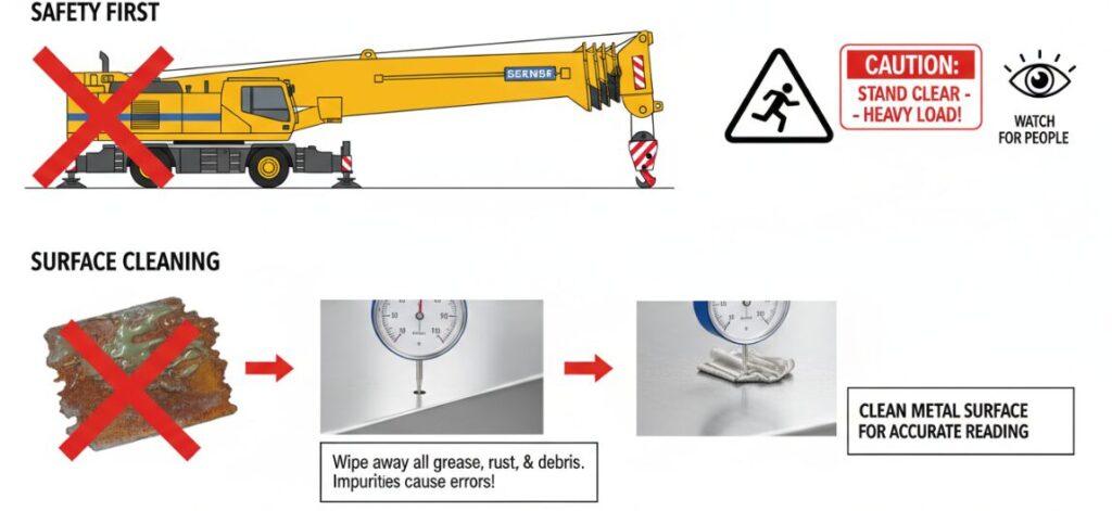
Surface cleaning: Dial gauge probe must be in contact with a clean metal surface. Even a little grease, rust or patent leather can make the result deviate by a few tenths of a millimeter, and this data cannot be seen. It is necessary to wipe the measurement area clean.
Erection of dial gauge:
Base: The magnetic base is sucked on the side that does not move (usually the chassis or frame). It must be sucked and cannot be shaken.
Probe: The probe is vertically mounted on the rotating side (the end face of the vehicle or bearing). It must be kept vertical so that the real axial displacement is measured.
Single Row Ball Slewing Bearing
Single-row ball slewing bearings are divided into internal tooth, external tooth and toothless structure, which are suitable for a variety of transmission needs.
Double Row Ball Slewing Bearing
Double-row ball slewing bearings are specially designed for super-heavy load scenarios.
Slewing Bearing With External Gear
The external gear internal flange slewing bearing integrates the advantages of external gear transmission and internal flange mounting.
Slewing Bearing With Internal Gear
The internal tooth and external flange slewing bearing is characterized by the combination of internal tooth transmission.
Slewing Bearing Without Gear
Gearless double flange slewing bearing is light weight and compact.
Cross Roller Slewing Bearing
Single-row cross roller slewing bearing adopts roller cross layout, large contact area, can synchronously and efficiently withstand axial and radial loads and overturning moment,
Step-By-Step Measurement Procedure
The actual execution of the “slewing bearing wear measurement” must follow the logic of the load reversal:
Establish a zero point (static load): the machine stops, but in order to read, you have to hold the gap to the maximum in one direction. Usually the boom is extended or weighted to create a forward center of gravity. At this time, the bearing was full of force in this direction, and the watch needle returned to zero.
Apply reverse torque: use the hydraulic system (such as the bucket to support the ground gently press down), the front end of the car slightly up. This action is done, the center of gravity shifts, and the bearing “sways” backwards.
Read deviation: stare at the dial. As the load reverses, the boarding will move relative to the alighting, and the reading on the meter is the true total axial clearance at this point.
Four-Point Detection Strategy
Why do we have to measure the four points of 0 °, 90 °, 180 ° and 270 °? The slewing bearing is rarely worn evenly. Most heavy equipment (like excavators and cranes) have a habitual “work area” that only grinds that piece for a long time. It is easy to miss the largest wear point by measuring only one point.
Rotate and repeat: after measuring the first point, turn the car 90 degrees, reset to zero, reverse the load again, and record the data. You have to walk to all four positions so that you can get to the bottom.
Data Analysis And Service Limits
After the data of the four quadrants are obtained, pick out the largest value and check it with the OEM specification.
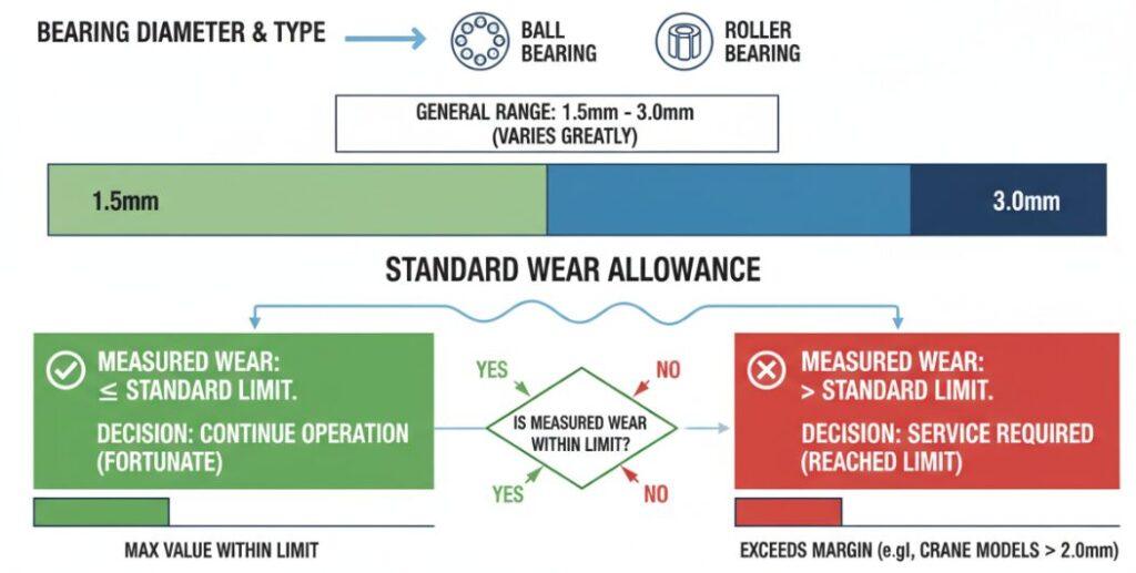
Standard allowance: Although the general wear allowance is between 1.5mm and 3.0mm, it is highly dependent on the bearing diameter and type (ball or roller type, which varies greatly).
Decision:
Tolerance range: If the maximum value is within the limit, it is fortunate that the machine can continue to dry.
Exceeding standard: If the specified margin is exceeded (for example, some crane models exceed 2.0mm), the service limit is reached.
Accurate “slewing bearing wear measurement” is not only a maintenance work, but also a life-saving procedure. Through the swing test-stand table, reverse load, check all four points-you can accurately grasp the health of the equipment. Finally, once found that the amount of wear exceeds the standard, must give priority to replacement, don’t take any chances, structural failure will really happen.
Author: David Thorne
“Hi, I’m a Senior Mechanical Engineer with over 17 years of experience in heavy equipment maintenance. I specialize in slewing bearing diagnostics and structural integrity analysis. I hope to help maintenance teams perform accurate wear measurements to extend equipment life and ensure operational safety.”
