SWBTEC


Slewing Bearings: How to Match Structure to Duty
A rotating platform can look simple until the bearing beneath it must carry weight, resist a side load, and keep the structure steady as an off-center load tries to tip it. That is the job of slewing bearings. They connect two parts of a machine, support their relative rotation or oscillation, and carry a combination of axial load, radial load, and overturning moment at one mounting position.
The useful question is not merely whether a bearing fits the available diameter. It is whether its internal structure, gear arrangement, mounting interface, and lubrication plan fit the machine’s real duty. A bearing that looks right in a catalog can still be the wrong choice when the load is applied through a flexible frame or the machine repeatedly swings through a small angle.
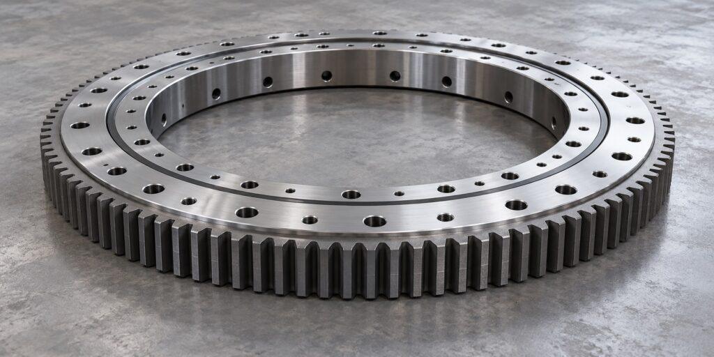
What is inside a slewing bearing?
A typical unit has inner and outer rings with raceways between them. Balls or rollers transfer load across those raceways. Depending on the design, separators, spacers, or a cage keep rolling elements apart. The rings also provide mounting holes, and may carry gear teeth, seals, and lubrication passages.
One ring is connected to the stationary structure and the other to the rotating structure. Which ring turns depends on the machine. That detail affects the bolt interface, drive layout, access for inspection, and the way loads enter the bearing.
The bearing supports rotation; it does not create it. If the machine uses a geared ring, a matching pinion and drive train must deliver torque. A toothless ring needs another drive arrangement. A complete slew drive goes further by integrating a bearing with transmission components and a housing, so its supply scope is different from that of a standalone bearing.
Start with loads that occur together
Axial force acts along the rotation axis. Radial force acts across it. Overturning moment comes from loads applied away from the bearing’s reference plane or rotation axis. These three demands interact inside the raceway and in the bolted joint. The largest value of each may occur in a different operating event, so combining unrelated maximum figures can misrepresent the real case.
Build a short operating-case record instead. For each relevant condition, note the simultaneous axial force, radial force, and overturning moment, plus the motion and duration. Include normal operation, starting and stopping, unusual but credible loads, and any parked or holding condition that matters for the equipment. If a geared bearing is involved, record the pinion force and any reverse or braking load as well.
The candidate model should be checked against its own raceway load curve and bolt load curve. Passing one check does not make the other unnecessary. The supporting structure must also be sufficiently stiff and flat for those calculations to remain meaningful: frame distortion can shift load onto a smaller part of the raceway even when the nominal bearing capacity appears adequate.
Choose rolling elements for the duty
Slewing bearings are available in ball and roller arrangements. A single-row four-point contact ball design can be a compact starting point for combined loads. Double-row ball and multi-row roller arrangements are other candidates when the load pattern or stiffness requirement changes. Crossed-roller designs are relevant where the application calls for a different combination of load support and rotational behavior.
None of these names is a rating by itself. The choice depends on the simultaneous load cases, available envelope, stiffness and precision requirements, speed or swing angle, and the product’s actual design data. A small oscillation deserves particular attention because the same limited raceway area can be loaded repeatedly. Continuous rotation, intermittent indexing, and back-and-forth motion should therefore be described separately during selection.
Slewbearingtec’s product range includes single-row ball, double-row ball, three-row roller, and crossed-roller slewing bearings. That range provides possible structures to compare, but the correct model still depends on the machine’s load case and approved drawing.
Decide where the gear belongs
An external-gear bearing places teeth on the outside of a ring, making the mesh accessible around the outer circumference. An internal-gear bearing places teeth toward the center opening. A toothless bearing has no integrated gear teeth. Slewbearingtec offers all three arrangements.
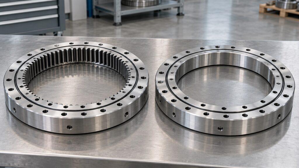
Select the arrangement around the whole machine, not the bearing alone. Confirm where the pinion can fit, the required center distance, which ring rotates, how the teeth will be lubricated and protected, and whether there is room to inspect the mesh. For a toothless design, specify the separate method that will drive or position the rotating part. Gear location does not tell you the rolling-element structure or load rating; those need their own review.
Check the interface before approving a replacement
Overall diameter is only one part of interchangeability. Compare the inner and outer diameters, height, mounting-hole pattern, locating features, gear data, clearance or preload, and the intended rotating ring against a controlled drawing. Then compare the actual load capacity and operating limits. A three-dimensional model can help with space and interference checks, but it is not a substitute for the approved dimensional and technical record.
Replacement work needs extra care. A worn part may no longer reflect its original geometry, and an old installation may contain repairs or changes that were never documented. Record the machine identification, original part designation, service history, and any observed damage, then reconcile measured interfaces with the approved drawing before ordering.
Installation and lubrication are part of the selection
Clean, flat mounting surfaces and even bolt preload help the bearing carry load as intended. The installation instructions for Slewbearingtec products call for the marked soft zone and filling plug to be placed in a non-load or light-load area. The required bolt grade and tightening method should be checked against the product instructions and the joint design rather than guessed from ring size.
Lubrication also needs to reach the parts that actually move. A bearing may arrive with only a small amount of grease in its raceway, so installation lubrication must be confirmed before operation. A geared version may need a separate plan for its tooth mesh. During service, watch the seals and investigate unusual noise, impact, or a sudden rise in drive effort before continuing to run the machine. Water and foreign matter should be kept out of the raceway.
A practical specification to send with an inquiry
The most useful inquiry describes the machine and mechanism, the simultaneous load cases, the desired rotation or oscillation pattern, and the space available for the ring and drive. Add the fixed and rotating sides, mounting drawing, gear preference, environmental exposure, access for lubrication, and any precision or stiffness requirement. For a replacement, attach the original drawing and identification when available.
With those inputs, a supplier can compare candidate structures and document the checks that matter: raceway and bolt capacity, gear interface, mounting fit, operating behavior, and maintenance access. That is a sounder basis for choosing slewing bearings than a shared name or a matching outside diameter.