SWBTEC


Slew Drive Selection: Match Loads, Motion and Holding Needs
When adding 1 low-speed rotary shafts to the equipment, the common question is: Do you still need an independent rotary bearing if the rotating parts bear weight, lateral force and overturning moment at the same time? The deceleration mechanism that transmits the torque alone usually cannot explain how the entire rotary shaft bears. Slew drive (slewing drive) combines the support, transmission and installation interface together, but whether it can be used for a certain equipment still depends on the load and motion conditions.
First, Clearly Distinguish Between The Support And Drive Boundaries.
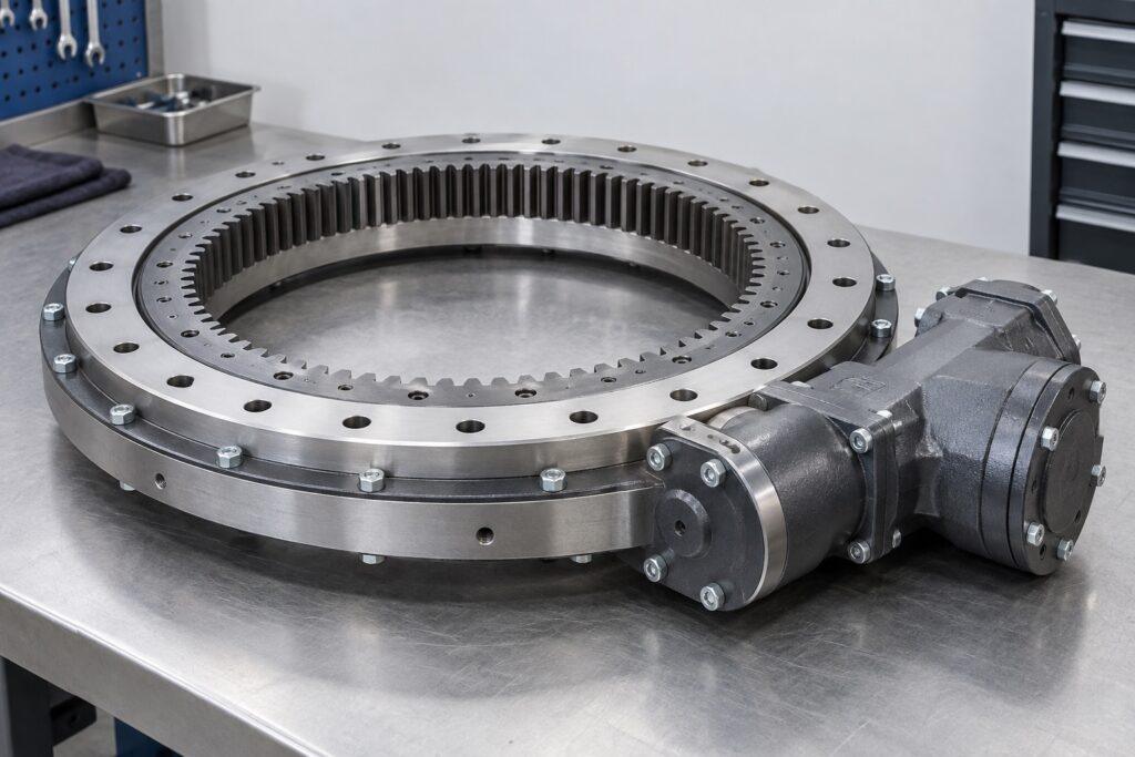
The slewing bearing connects the stationary and rotating components of a machine, transmitting axial forces, radial forces, and overturning moments while permitting relative rotation. A toothed slewing bearing can mesh with an external pinion, but it does not necessarily include a drive, housing, or brake. The slewing drive integrates the slewing bearing, worm gear or gear pair, housing, and input interface into a single unit, simultaneously handling load-bearing and torque transmission.
This distinction will directly affect the scope of procurement. The drawing specifies “slewing ring drive,” which may refer to a slewing system composed of multiple components; “slew drive gearbox” may also refer solely to the input-side reduction gearbox. When confirming the quotation, the assembly drawing and supply list shall be required to indicate the support, transmission pair, housing, motor or hydraulic motor, reducer, brake, encoder and fastener respectively. Similar names do not necessarily imply identical supply scopes.
Verify The Load-Carrying Capacity Using Simultaneously Applied Loads.
When selecting equipment, you cannot simply provide just the “maximum weight.” The weight of the workpiece or working device forms an axial force; the lateral action forms a radial force; the overturning moment is also formed when the load center deviates from the rotary axis. Starting, braking, impact, or reversing operations may cause these loads to be superimposed at the same time. The load, acting direction, occurrence frequency and duration of each group at the same time shall be listed according to the actual working conditions, instead of combining several maximum values that do not occur at the same time into one working condition.
Both the support unit of the rotary drive and the connecting bolts must withstand these loads. The load-bearing curves, applicable operating conditions, and installation requirements provided by the supplier shall correspond item by item to the equipment’s load combinations. Even if the main body meets the catalog specifications, deformation of the base, an uneven mounting surface, or insufficient bolted connections can still alter the load distribution on the raceway. Therefore, when verifying dimensions, it is also necessary to simultaneously check the fixed side, the rotating side, the mounting holes, the connection structure’s stiffness, and the available installation space.
The Driving Torque And The Holding Torque Are Proposed Separately.
Being able to turn and being able to stop are two requirements. The output torque must accommodate normal operation, acceleration, direction reversal, and potential peak loads; the holding torque corresponds to external forces acting after the system has come to a stop. Reverse loads can also drive the transmission mechanism through the output end. The selection table shall specify the operating torque, peak torque, holding load, and permissible backdriving conditions separately; no single value may be used to substitute for the other requirements.
Worm-type rotary drive is suitable for scenarios that consider compact arrangement, large reduction ratio and low speed and high torque; pinion-type scheme can also be used as another 1 of transmission options. When comparing the two, use the same output torque, rotational speed, duty cycle, and environmental conditions, then evaluate efficiency, temperature rise, backlash, and maintenance requirements. In particular, one should not assume that a device has reliable self-locking capability simply because it uses a worm gear. If the parking position fails, it may pose a safety risk; therefore, the fault state and the braking or mechanical locking scheme should be defined separately.
Incorporate The Motion Cycle Into The Technical Specifications.
For the same rotary axis, the constraints governing continuous rotation, reciprocating oscillation, and intermittent positioning are not the same. The requirements shall specify the rotation angle, output speed, acceleration, number of starts and stops per hour, working and stopping time and rotation direction. The gear ratio only describes the kinematic relationship between the input and output; it cannot, by itself, determine efficiency, output torque, or positioning accuracy.
If the equipment requires angular positioning, it is also necessary to specify the allowable backlash, repeatability, and position feedback configuration. Encoders can provide feedback, but backlash in the transmission, bearing stiffness, the housing, the mounting structure, and the control method all influence the final positioning accuracy. The encoder resolution alone is insufficient to determine whether the entire system can reach the target position.
Installation And Maintenance Conditions Determine Whether It Can Be Used For A Long Time.
The installation orientation affects lubrication distribution, sealing performance, and drainage conditions. If the equipment has dust, water, shock or vibration, the environmental conditions should be submitted together with the maintenance space. The closed housing can reduce the chance of direct exposure of transmission components, but the protection ability under any working conditions cannot be extrapolated accordingly; it is still necessary to check the sealing, grease filling, drainage and heat dissipation requirements of specific models.
After installation, tightening, lubrication, and functional checks should be performed in accordance with the product instructions. In case of abnormal temperature rise, noise, vibration, leakage or change of return clearance during use, stop the machine to find out the cause; the worm or pinion clearance cannot be adjusted without authorization to cover up the problem. The maintenance interval should also be determined in consideration of the load, speed, temperature, contamination level, and duty cycle.
Establish Comparable Inquiry Conditions.
A requirement document for comparison should include load combinations, output torque, speed and duty cycle, holding requirements, mounting orientation, environment, interface dimensions, and the scope of accessories. The supplier is requested to provide the model boundary, bearing and transmission verification basis, installation requirements and items that need to be confirmed by the whole machine under the same working conditions. Only by making such a comparison can we identify a slewing solution that is both installable and capable of fulfilling the task, rather than merely two assemblies with similar external appearances.