SWBTEC


Custom Slew Drive Assembly & Slew Ring System Specs
Customizing slewing drive assemblies and slewing bearing systems for equipment selection requires a precise engineering match between the equipment’s overturning moment limits, dynamic output torque, and hydraulic/motor interface. Standard enclosed drives on the market tend to fail under extreme tilt loads because their standardized hourglass worm and conventional gear ratios simply cannot handle the impact loads experienced by specific OEM equipment. This technical specification guide details the precise metallurgical data, dimensional tolerances and integration protocols required to design a complete non-standard rotary system. By introducing the engineering framework and metallurgical specifications described below, R & D engineers can fundamentally eliminate gear spalling, backlash jitter, and prevent catastrophic self-locking failures in heavy boom lifts, mining excavators, and solar tracking arrays.
D.R. I .V.E. Integration Matrix For Custom Assemblies
Many OEM designers’ prototypes are scrapped because they treat the slewing bearing system as an isolated component, rather than a part of the entire power transmission system. The application of the D.R. I .V.E. matrix ensures a non-destructive transfer of mechanical power from the motor shaft to the final rotary flange.
Comparison Of Working System Curve And Peak Output Torque
The peak torque on the standard catalog tends to mask the thermal limits of the equipment. Custom slewing drives must establish accurate duty-cycle Profiling based on actual operating parameters. We calculate the exact running torque for 100% continuous and 10% intermittent. By adjusting the coincidence of the enveloping worm gear (increasing the 3-tooth meshing in the standard case to 5-7 teeth simultaneously), its heat dissipation capacity and continuous dynamic torque output will increase exponentially without increasing the physical size of the housing.
Integrated Response To Radial/Axial Shocks
The asymmetric impact loads generated by heavy machinery are sufficient to rupture a standard cast iron housing. To this end, we use ductile iron (QT450-10 or QT500-7) to customize the housing. The raceway of the internal slewing bearing is specially induction hardened to a hardness of 58-62 HRC and the target effective hardening depth (ECD) is set to 6mm, so as to ensure that the core still retains the strength and toughness of 260-290 HB, thus being able to perfectly absorb the severe radial impact from the stone crusher or forestry grab.
Engineering Design Of Involute Meshing And Zero Backlash
High-precision automation equipment requires extremely high absolute accuracy of position. Standard drives usually have a backlash of up to 0.15 °, which can cause extremely dangerous resonance oscillations at the end of the long boom. By customizing the eccentricity of the worm shaft and adopting the double worm structure, we realize the gear meshing state of negative clearance (preload). This rigorous optimization of involute meshing can compress the backlash limit of the system to below 0.015 °.
Electrical/Hydraulic Interface Matching
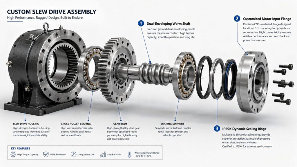
Common motor flanges tend to slow down the assembly line and have to cobble together adapter plates. We chose CNC machining directly on the rotary drive housing to precisely customize the input flange, spline size and keyway tolerances. You only need to provide the CAD data of Danfoss (Danfoss) hydraulic cycloid motor or Siemens (Siemens) servo motor, we can process the direct connection interface of 1:1 direct installation.
Engineering Trap: The Illusion Of Holding Torque
Mechanical engineers often underestimate wind shear and gravity loads when selecting slewing bearing systems. This typical selection error can easily lead to structural collapse of equipment under power failure.
Engineers often select drives based only on the “dynamic output torque” required by the rotating load, but directly ignore the “holding torque” (static self-locking capability) that the equipment must have. Standard single worm drives rely entirely on gear friction to achieve self-locking. Imagine that when the boom of an aerial work truck is fully extended in a storm, the overturning moment caused by the wind will produce a huge reverse torque. If the lead angle of the worm gear exceeds the critical friction angle, the system will reverse drive (reverse drag), and the teeth of the bronze gear will be completely stripped and flattened in an instant.
We customize the drive by modifying the lead angle for the static holding torque required by the customer. In order to absolutely meet the safety compliance standards of the passenger lift, we have integrated a hydraulic brake assembly directly at the connection between the motor and the worm input shaft, ensuring “zero slip” of the mechanical parts in the event of a catastrophic load event “.
Complete Customized Baseline Parameters
See the customizable benchmark parameters below. These original technical specifications will be adjusted and optimized through finite element analysis (FEA) to exactly match your set overturning moment and speed targets.
| Drive Series | Output Torque Capacity (kN·m) | Holding Torque Capacity (kN·m) | Tipping Moment Capacity (kN·m) | Gear Ratio Options | Max Input Speed (RPM) | Custom Flange Types |
|---|---|---|---|---|---|---|
| 7-inch | 1.2–1.8 | 3.5–5.0 | 8–12 | 31:1 / 47:1 / 62:1 | 2,000 | SAE A, Metric ISO |
| 9-inch | 2.5–3.8 | 7.0–10.5 | 18–28 | 31:1 / 47:1 / 62:1 / 78:1 | 1,800 | SAE A/B, Metric ISO |
| 12-inch | 5.5–8.5 | 15–24 | 45–70 | 47:1 / 62:1 / 78:1 / 102:1 | 1,500 | SAE B, Metric ISO |
| 14-inch | 9.0–13.5 | 26–38 | 80–120 | 62:1 / 78:1 / 102:1 | 1,300 | SAE B/C, Metric ISO |
| 17-inch | 16–24 | 45–68 | 150–230 | 78:1 / 102:1 / 125:1 | 1,100 | SAE B/C, Metric ISO |
| 21-inch | 30–45 | 85–130 | 300–450 | 102:1 / 125:1 / 150:1 | 900 | SAE C, Metric ISO |
| 25-inch | 55–80 | 160–240 | 550–800 | 125:1 / 150:1 / 180:1 | 750 | SAE C, Metric ISO |
2026 Standard: IP69K Class Dynamic Seal
Abrasive dust and high-pressure flushing can often destroy the internal raceway within a few months. In heavy-duty applications, we have completely eliminated the standard nitrile rubber (NBR) lip seal. Your custom slewing drive assembly will be equipped with an integrated IP69K class seal architecture with fluorine rubber (FKM/Viton) labyrinth seals. This special structural upgrade completely physically isolates the gear meshing area from the internal bearing grease, allowing the worm gear (using extreme pressure gear oil) and the raceway (using NLGI Class 2 lithium grease) to be separately filled with lubricating media of different viscosities.
Real Case: Redesign Of 120 Ton Aerial Work Platform (AWP)
A leading European manufacturer of aerial work platforms found in their tests that the boom would shake violently up to 40 meters when using standard commercial rotary drives. The gear backlash of only 0.2 ° is amplified by the lever effect to a lateral wobble of 150mm in the operating basket.
Our engineering team designed a completely customized slewing bearing system. We introduced a dual-worm architecture (I. e., two worms driving the center inner ring at the same time) and machined gears with fractional pitch to achieve an interference fit.
Final result: This custom assembly sharply reduces system backlash from 0.2 ° to 0.015 °. The double worm configuration will greatly increase the torque by 65%, completely eliminate the shaking problem of the operating basket, and enable the main engine factory to successfully pass the strict CE safety certification without changing the configuration of the main hydraulic motor.
Frequently Asked Questions (FAQ)
What is the difference between a slew drive assembly and a bare slewing bearing?
Bare slewing bearings only provide rotation and load support, which means you need to design your own external pinion, motor mount and protective housing. The rotary drive assembly is a fully enclosed, self-sufficient modular system. It fully integrates the bearing, drive worm gear, cast housing and motor interface in a single, direct plug-and-play assembly.
How do I specify the correct motor flange for a custom slewing system?
You must provide dimensional drawings of the specific hydraulic or electric motor you are using. Our engineers need to obtain the positioning boss (stop) diameter, bolt distribution circle diameter (BCD), shaft length, and spline/keyway specific parameters (e. g. SAE J498b spline standard). After confirming the data, we will directly process the input flange of the drive to make it perfectly engage with your motor, completely eliminating the adapter plate.
Can the rotary drive assembly run continuously at high speed?
Absolutely not. The rotary drive uses a worm gear structure, which will generate a lot of friction heat during operation. The standard enclosed drive is designed for intermittent operation and low speed (usually less than 2 RPM) conditions. If high-speed continuous rotation is required (e. g. centrifuge or fast indexing disk), we must customize the system with spur gear or planetary gearbox structure and mandatory oil circulation cooling device.
In a revolving system, what does “double envelope (dual-enveloping)” mean?
Ordinary standard cylindrical worm usually only at the same time with the slewing bearing 1 to 2 teeth meshing. The double-enveloping worm is processed into an hourglass shape, which can perfectly wrap and fit the outer arc of the slewing bearing. This design can achieve 5 to 11 gear teeth meshing at the same time, without increasing the physical size of the housing, the torque capacity, impact resistance and holding torque up to 300 percent.
How to prevent sea water and moisture from seeping into the marine rotary drive?
Marine and offshore applications have extremely stringent requirements for upgrading materials and seals. We customize the assembly by using multi-lip Viton seals, vacuum infiltrated shell castings, and special marine-grade coatings such as zinc-rich epoxy primers that fully comply with C5-M corrosion protection standards. In addition, all breathing valves will be upgraded to polytetrafluoroethylene (PTFE) breathable membrane, which can not only ensure the balance of internal and external pressure, but also keep the water out.