SWBTEC


Slewing Gear Backlash: A Full-Ring Installation Check
A geared slewing bearing can turn smoothly at one position and still bind or knock elsewhere. The pinion meets a different section of the ring as the machine rotates, and the gap between the teeth can change around the circumference. That is why setting a slewing gear from a single convenient measurement can leave an installation problem hidden.
Backlash is the clearance between mating gear teeth. It allows for manufacturing variation, assembly error, structural movement and temperature effects. Too little can raise tooth load, friction and heat; too much can add impact, noise and lost motion. The correct value comes from the approved gear and equipment drawings, not from a universal rule of thumb.
Start With The Actual Drive Layout
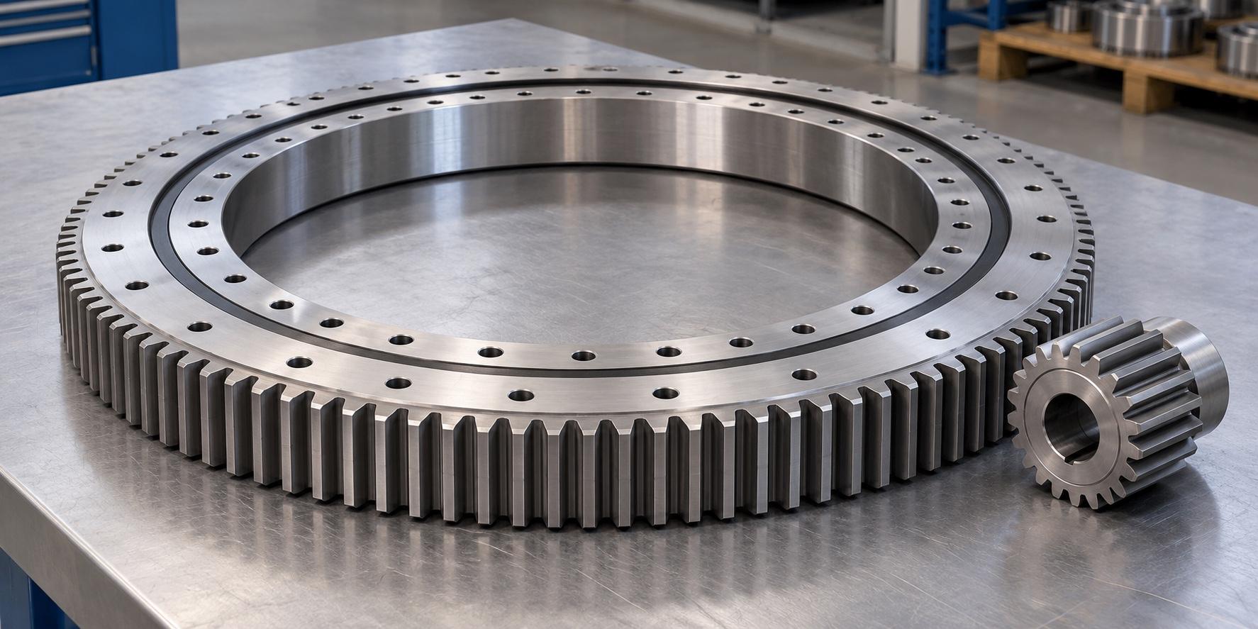
Before adjusting anything, identify the parts in the drive. A geared slewing bearing combines a load-carrying raceway with teeth on one ring. A pinion drives those teeth, usually through a reducer powered by an electric or hydraulic motor. The bearing carries axial and radial loads and overturning moment; the gear pair transmits turning torque. Checking one function does not validate the other.
On an external-gear bearing, the teeth sit around the outside and the pinion approaches from the perimeter. An internal-gear bearing places the teeth inside the ring, so the pinion occupies part of the central opening. Slewbearingtec offers external-gear QW and internal-gear QN slewing bearing series. The drawing still needs to show which ring is fixed, which rotates, the pinion axis, and the intended direction of drive. Tooth position alone does not establish those details.
Confirm The Gear Pair Before Setting Clearance
A ring and pinion with similar-looking teeth may still be incompatible. Check the specified module, tooth count, pressure angle, profile shift, face width and accuracy requirements for both components. Confirm the intended center distance, mounting position and tooth-surface condition as well. An outside diameter or a matching bolt pattern cannot stand in for the gear data.
The supporting structure deserves the same attention. If the mounting faces distort the bearing, the position of the gear ring relative to the pinion changes. Moving the pinion may improve one contact point while worsening another. Correct the support and mounting condition against the equipment requirements before treating backlash adjustment as the cure.
Measure Where The Drawing Specifies
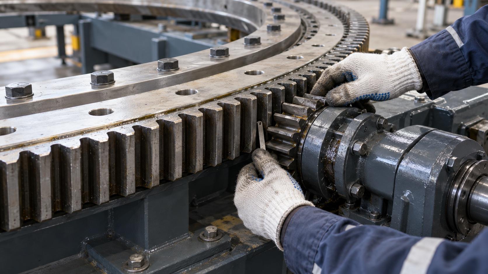
Use the manufacturer's specified ring position, measuring method and acceptance criteria when setting the initial backlash. Record the location and tool used. Then turn the assembly through a complete revolution and check the clearance at multiple positions. Radial runout, mounting eccentricity and structural deformation can all change the gap as different teeth pass the pinion.
A free-running section is not proof that the tightest section has enough clearance. Likewise, a single tight spot should not be dismissed because most of the rotation feels normal. If the readings vary beyond the approved limits, investigate the ring, pinion mount and supporting structure before releasing the equipment.
Look At Tooth Contact, Not Clearance Alone
After setting the pinion position, inspect the contact pattern across the tooth face at the locations required by the installation procedure. A narrow mark at one edge may indicate an alignment or deflection problem even if backlash appears acceptable. Check the pinion axis and center distance, then repeat the contact and clearance checks after any adjustment.
This is especially relevant when the machine reverses frequently. Each reversal changes which flanks carry the load. The bearing load calculation and the gear-tooth load calculation should both reflect the real duty cycle; passing either check by itself does not establish that the complete slewing system is suitable.
Keep The Gear Teeth Lubricated And Accessible
Grease in the bearing raceway does not mean the open gear teeth have been lubricated. Confirm the tooth lubricant and replenishment method for the load, speed, temperature, materials and operating environment. Also check compatibility with seals and any lubricant left on the assembly. A shipping protectant should not be assumed to serve as working gear lubricant.
The guard should limit entry of water, grit and loose material without blocking inspection, relubrication or drainage. An external gear can be particularly exposed at the machine perimeter; an internal gear is sheltered by nearby structure but is not automatically sealed.
What To Record Before Commissioning
Keep a traceable record of the ring and pinion identification, the approved drawing revision, the measuring positions, backlash readings around the ring, contact observations and lubrication status. Note which ring rotates and which component was adjusted. If a later knock occurs at a particular rotation angle, those records help distinguish a local tooth problem from a raceway, reducer, brake or structural issue.
If there is broken or badly damaged tooth material, inspect the mating pinion, shaft, center distance and source of shock before replacing parts. Installing a new ring against an unsuitable pinion or unchanged mounting problem can repeat the damage. A full-ring check gives the replacement a better starting point than a single clearance reading.