SWBTEC


Slewing Gear Bearing Specs: Gear Slew Torque Unlocked
At many construction sites and on heavy‑duty machinery, what is commonly referred to as a “slewing ring gear” or a “geared slewing bearing” is, in essence, a heavy‑duty rotary joint incorporating either an internal or external gear ring. It is specifically designed to transmit the substantial torque generated by the drive motor directly and efficiently to the equipment’s rotating assembly.
If the old gear ring breaks and you need to replace it, there’s a critical prerequisite: you must precisely match your hydraulic motor’s output torque with the new bearing‑gear assembly’s “maximum allowable tangential force.” What happens if the selected parameters don’t match? The consequences are clear: either, as soon as power is applied under heavy load, the gear teeth will shatter right in front of you; or the motor will be throttled to a standstill and burn out. Today, I’ll lay out the underlying logic for nailing down torque parameters, hand you a selection matrix that guarantees no failures, and also expose those installation pitfalls on site that can instantly scrap a brand-new slewing bearing.
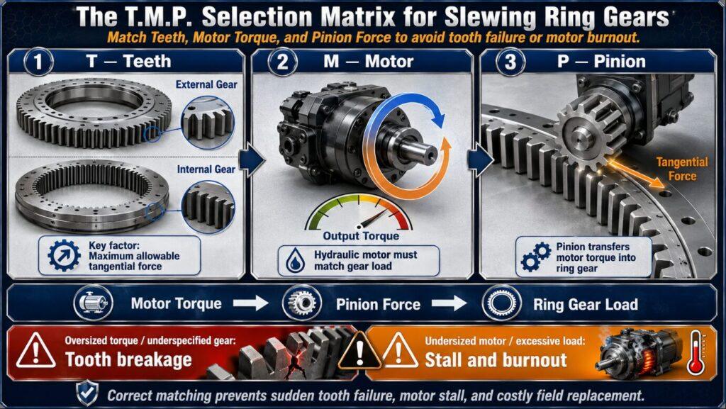
T.M.P. Torque matching matrix: choosing the right gear without asking for help
If you want to set the specifications for the replacement slewing bearing, you have to calculate the mechanical relationship between the main ring gear and the drive unit clearly. In order to help the maintenance masters on the scene to buy the right accessories without taking a mechanical engineering degree, I summarized a set of “T.M.P. matrix” (I .e. Teeth gear ring, Motor motor, Pinion pinion).
T-Teeth (ring gear): with internal teeth or external teeth?
The structure of your machine itself determines whether you need internal or external teeth. The tooth length of the external tooth slewing bearing is on the outer ring, and the diameter of the pitch circle is larger, so it can withstand a higher limit torque, and the maintenance inspection can be seen at a glance. The internal gear slewing bearing hides the teeth in the inner ring. Although it sacrifices a little limit torque limit, it can perfectly protect the meshing parts and completely isolate the damage of the harsh environment such as sediment and gravel on the construction site.
M-Motor (motor): calculate quasi-tangential force
Please memorize an iron law: the output torque of your drive motor must not exceed the maximum allowable tangential force (Tangential Force) of the slewing bearing. How? Just divide the maximum torque of the motor by the radius of the pinion. If the calculated force exceeds the rated limit calibrated by the manufacturer, once heavy load is encountered, the huge force of the motor will directly tear off the gear teeth on the big gear ring like a hand-torn chicken.
P-Pinion (pinion): the hardness must be suitable
The metal hardness of the small gear must match that of the large ring gear. If you take a steel pinion that has been deeply hardened and “head-to-head” with an ordinary large gear ring that has not been hardened, it is purely destructive. This “cutting effect” is terrible. In a few weeks, the tough pinion can grind the huge ring gear into a pile of metal powder.
The measured data speak: why does the ring gear break teeth?
The root cause of the broken tooth is one: the torque applied to it exceeds the strength limit of the core of the gear metal. In order to find out the gap, our team specially did a destructive torque test, taking the standard unhardened gear ring and the bearing treated with “tooth surface local quenching (LTQ)” to fight.
| Gear Treatment Process | Surface Hardness | Maximum Tangential Force Before Fracture | Field Results |
|---|---|---|---|
| Unhardened Plain Carbon Steel | 180 HB | 45 kN | Under impact loading, the gear teeth bend directly and fail by shear fracture. |
| Localized Tooth Quenching (LTQ) | 55 HRC | 135 kN | The tooth surface remains hard and rigid, while the core retains high toughness, preventing brittle tooth fracture. |
It is clear from the data that the LTQ treatment can directly triple the torque resistance of the slewing bearing. Only the surface of the teeth is hardened, and the core body inside the gear is kept soft and tough. This “outer rigid and inner soft” structure can be like a spring, strongly absorbing the severe impact force from the motor without breaking.
Lao shifu’s guide to avoiding pits: don’t roll over during on-site installation
Trap 1: The “zero backlash” motor-burning disaster of taking everything and leaving nothing behind (The Backlash Burnout Trap)
Many novice technicians like to install the pinion gear by pressing it hard against the slewing ring, which is tantamount to sentencing the drive motor to failure. Gear meshing must incorporate a small, dedicated clearance known in the industry as “backlash.” This clearance accommodates thermal expansion and contraction during operation, as well as manufacturing tolerances. If no clearance is left and the parts are jammed tight, extremely severe friction will result. The motor will overheat severely as it tries to forcibly turn the gears, ultimately burning itself out. Take this advice: before tightening the motor bolts, carefully use a feeler gauge to set the side clearance to the manufacturer’s specified value.
Trap 2: Ignoring the gear’s “jump mark” (Ignoring the Gear Jump Mark)
All high-quality slewing bearings manufactured by reputable major manufacturers will invariably feature a painted line or a stamped steel mark on the gear ring. This mark indicates the “gear radial runout maximum point” (that is, the most protruding, highest point on this gear tooth). But the construction-site repairman often pretends not to see it. Key point: You must adjust the pinion side clearance exclusively at this marking point! If you adjust the backlash at any other point on the gear ring, when the machine reaches this highest position, the large and small gears will jam hard, causing an immediate catastrophic failure.
People Also Ask (FAQ)
What is the difference between a toothed slewing ring and an ordinary bearing?
Ordinary bearings can only make people turn smoothly, and you have to have another set of driving device. The slewing bearing directly engraves the inner or outer teeth on the bearing ring, which can not only carry tons of mechanical heavy loads, but also directly act as the main drive gear of the whole machine.
How do you lubricate this thing?
Remember, the gears and internal raceways need to be maintained apart. The tooth surface (whether internal or external) must be directly coated with extreme pressure (EP) open gear grease with a brush or automatic spraying system. As for the internal steel ball, you have to use a grease gun to drive lithium-based bearing grease into the grease nipple on the slewing ring.
Why does my slewing bearing always break teeth?
Basically, these 3 low-level mistakes cannot be escaped: first, the severe impact load exceeds the limit of tangential force; second, the tooth side clearance is not adjusted, causing the gear to jam and hold back; third, the middle of the gear is rolled in. Foreign objects (such as stones or bolts) were crushed abruptly.
Can the broken rotary gear be repaired?
Don’t dream, heavy slewing bearing broken teeth is absolutely impossible to repair. If you try to save trouble to weld a lump of new metal to the broken tooth, the high temperature will directly destroy the structural integrity of the whole gear ring and 100% will cause secondary fracture. If it is broken, replace the whole bearing assembly honestly.
I want to buy a new accessory. How do I measure the gear size?
You have to figure out its modulus (metric) or diameter (imperial). The specific method is very simple: count the total number of teeth on the broken gear ring, and then measure the outer diameter of the gear ring with a caliper. Throw these two accurate data to the manufacturer, and they will be able to reverse calculate the correct gear profile parameters for you.