SWBTEC


Master Worm Drive Slew Ring & Worm Slew Drive Selection
When selecting a worm gear rotary drive, engineers must comprehensively consider the dynamic overturning torque and thermal expansion limit to ensure that the equipment can provide an absolutely reliable zero-reversal (self-locking) holding torque under heavy load conditions. Thanks to the small lead angle of the worm shaft, the worm gear slewing support naturally has a mechanical safety braking function, which is why this structure is mandatory for aerial work platforms, mining excavators and solar tracking arrays. However, many B2B procurement engineers often only look at the static load table when selecting models, completely ignoring the continuous working system. This practice will inevitably lead to catastrophic lock failure of the gearbox on the construction site. To create the ultimate selection guide, our diagnostic engineering team conducted an in-depth analysis of 150 OEM slewing mechanism failure cases. Next, we’ll break down for you the math matrices, envelope tooth pattern differences, and thermal expansion traps that system architects must master when choosing the perfect model.
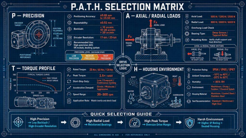
PATH Selection Matrix
By introducing PATH Selection matrix, system architecture designers can evaluate rotary drive against specific mechanical requirements, thereby fundamentally eliminating procurement errors.
- Accuracy (Gap): Conventional applications typically allow a 0.1 °to 0.2° gap. However, high-precision radar antennas and concentrated solar trackers must adopt a double worm configuration with zero tooth gap to effectively prevent the target from drifting.
- Axial vs. radial loads: Before torque can be transmitted through the gear set, the raceways inside the equipment must be able to independently withstand all their own weight (axial load) as well as wind shear forces (radial load).
- Torque curve: Engineers must strictly distinguish between “overturn torque” (the force that attempts to pry the bearing apart) and “holding torque” (the rotational friction required to keep the suspended load stationary).
- Enclosure operating environment: For conventional construction equipment, ductile iron enclosures with protection class IP65 are sufficient. But if it is in marine engineering or extremely wear and tear mining environment, IP67 level sealing is mandatory and paired with customized polyurethane marine grade anti-corrosion coating.
Comparison of tooth types of envelope worm and cylindrical worm rotary drive
Drum (envelope) worm tooth types are capable of withstanding impact loads up to three times that of standard cylindrical worms by maximizing the physical contact area between metals. Conventional cylindrical worm shafts have a straight geometric profile and often only engage one or two bronze gear teeth at a time.
When subjected to heavy impact loads (such as when a crane boom suddenly pulls on a falling concrete block), 100% of the shear force is instantly applied to both gear teeth, triggering a direct mechanical fracture. In contrast, the drum-shaped enveloping worm perfectly fits the arc of the rotary support and can engage 5 to 11 wheel teeth simultaneously in an instant. This multi-tooth meshing mechanism distributes extreme shear stresses over an extremely large surface area, significantly improving the survival rate of the equipment when it encounters catastrophic overload.
| Specification | Cylindrical Worm Drive | Globoidal Enveloping Worm Drive |
| Tooth Engagement | 1 to 2 teeth simultaneously (straight geometry) | 5 to 11 teeth simultaneously (wraps around the slewing ring curvature) |
| Shock Load Capacity | Standard (100% of shear force transfers to 1-2 teeth, risking mechanical fracture) | Up to 3 times higher (distributes extreme shear stress across a massive surface area) |
| Manufacturing Cost* | Lower (straight cylindrical geometry is standard and simpler to machine) | Higher (complex hourglass curvature requires advanced, precise machining) |
| Best Use Case | Predictable, steady-load applications without risks of sudden, heavy impacts | Heavy-duty applications prone to extreme impact or catastrophic overloads (e.g., cranes catching falling loads) |
Expert Pit Avoidance Guide: Thermal Expansion Stuck Traps
Many purchasing engineers used the rotary drive with standard clearance directly on continuous operation, causing thermal expansion and jamming, and eventually destroyed the expensive machine.
The factory standard worm drive will retain a tiny gap between the worm thread and the gear teeth, which is called the “tooth gap”. This gap is primarily intended to hold conventional grease and dissipate the surrounding heat. Once designers use standard drives in scenarios that require continuous, high-speed rotation (such as automated packaging spinning discs), the constant mechanical friction generates extremely high heat inside. Since bronze alloy gears expand much faster than steel worm shafts, this thermal expansion physically “eats up” the original tooth gap, forcing dry grinding between metal parts until the entire mechanism is violently locked. Therefore, for any application scenario where the rotation speed exceeds 1 RPM and continuous rotation is required, engineers must clearly request the manufacturer to adopt “high temporary load rate (high duty cycle) gap” when ordering.
Mechanical principles of torque retention and anti-reversal (self-locking)
As long as the model is selected correctly, the worm gear slewing drive can completely eliminate reverse slewing, and even without an external hydraulic brake, it can firmly lock the suspended heavy objects.
Physically, it all depends entirely on the worm shaft having a lead angle that must be less than the coefficient of friction between the steel and bronze gears. When the hydraulic or electric motor stops outputting power, the load tries to force the gear backwards to turn the worm. However, due to the vertical geometry of the two and the extremely high friction, the gear will be stuck by the threads. It is important to be vigilant that equipment designers must verify whether the high-frequency vibrations brought by external equipment such as diesel engines will reduce this dynamic friction coefficient, otherwise it is easy to trigger small slip phenomena.
Industrial Trends 2026: Acoustic Emission (AE) Condition Monitoring
Currently, top-tier original equipment manufacturers (OEMs) are integrating acoustic emission (AE) sensors directly into the slewing drive housing, enabling accurate predictions in the months leading up to mechanical failure.
Traditional maintenance methods often rely on regular grease sampling or measuring the physical tooth gap using a percentile chart. But this practice is often “with hindsight”, and by the time the problem is discovered, the teeth are usually already severely damaged. The acoustic emission sensor can keenly capture the high-frequency microscopic stress waves generated at the moment when the lubricating oil film breaks and friction between metals begins. By transmitting this data to the central console in real time through the Industrial Internet of Things (IoT) gateway, maintenance supervisors can plan targeted downtime maintenance in advance, such as replacing seals or injecting extreme pressure (EP) grease, effectively preventing bronze gears from falling to the point of complete scrapping.
Frequently Asked Questions (FAQ)
How To Calculate The Holding Torque Of The Worm Gear Slewing Drive?
When calculating the holding torque, the maximum applied radial and axial loads need to be multiplied by their respective distances to the central axis, while the wind load and the mechanical advantage (gear ratio) of the worm gear set must also be converted. The rated holding torque of the drive unit must be greater than this calculation and a safety factor of at least 1.5 times must be allowed.
What Is The Standard Tooth Clearance For Worm Gear Rotary Drive?
Industrial standard worm gear slewing drive tooth gaps are typically between 0.05 and 0.20 degrees. However, in high-precision application scenarios such as solar tracking or satellite dishes, dual worm or spring-loaded zero-tooth gap designs are used to completely eliminate mechanical play.
Can The Worm Gear Slewing Support Operate Continuously?
The standard models do not support continuous operation. Because the constant friction between the steel worm and the bronze gear generates excessive heat, which in turn causes thermal expansion and even jamming. If continuous operation is required, the internal clearance must be customized and synthetic high-temperature lubricants and active cooling systems must be used.
What Type Of Lubrication Is Required For Worm Gear Slewing Drive?
The use of extreme pressure (EP) lithium-based greases containing molybdenum disulfide or graphite additives is strictly required for worm gear rotary drive. These solid boundary lubricants are effective in preventing gluing wear of metals when subjected to extreme impact loads.
Why Is My Worm Gear Slewing Drive Failing Prematurely?
There are usually several reasons for premature failure: structural overload, uneven installation surface leading to raceway deformation, or severe water ingress completely destroying the lubricating oil film. In addition, if the standard drive is operated continuously without cooling, the aging and scrapping of bronze gears will be accelerated.