SWBTEC


Slewing Ring Bearing: What to Check Before You Specify One
A slewing ring bearing connects two machine structures while allowing one to rotate or swing relative to the other. It also carries a combination of axial force, radial force, and tilting moment at that connection. That makes it more than a large circular bearing: its rings, mounting bolts, support structure, and any drive components have to work together.
The name alone tells you little about the internal design. “Slewing ring bearing,” “slewing bearing,” and “slew ring bearing” are often used for the same broad product family. None of these terms identifies the rolling elements, number of rows, gear arrangement, or allowable load. A useful specification starts with the machine and its duty, then narrows down the bearing structure.
Start With The Loads That Occur Together
Axial force acts along the rotation axis. Radial force acts across it. Tilting moment tries to load one side of the ring more heavily than the other. In a crane or excavator, these effects can change as the upper structure moves, accelerates, brakes, or carries a different load.
Record the forces and moment for each meaningful operating condition, including their directions and whether they occur at the same time. A single maximum axial load is not enough. A candidate bearing must be checked against the combined load conditions for its specific design, along with the associated bolt connection. A bearing that passes a raceway load check may still be unsuitable if the mounting joint or supporting structure is inadequate.
Motion matters too. Continuous rotation, intermittent positioning, and repeated movement through a small angle do not expose the same region of the raceway in the same way. Note the angle, frequency, load during movement, and expected working cycle before asking for a life assessment.
Choose The Rolling Structure For The Duty
A single row, four point contact ball design is a compact starting candidate for combined loads. Double row ball designs add another row of rolling elements and can offer a different load path, but they also require the available axial space to be checked. Crossed roller designs use alternating roller orientations and may suit applications where stiffness or rotational accuracy is a major constraint. Three row roller designs separate load directions across multiple roller paths and can be considered for demanding combined loads when the machine provides a sufficiently rigid mounting structure.
These are design families, not performance rankings. Bearing diameter by itself does not establish capacity, and a category name does not establish accuracy or service life. Compare actual models using the same load cases, installation assumptions, and life target. For a replacement, changing from a ball design to a roller design—or changing the number of rows—calls for a fresh check of the load path and machine interface.
Treat The Gear As A Separate Decision
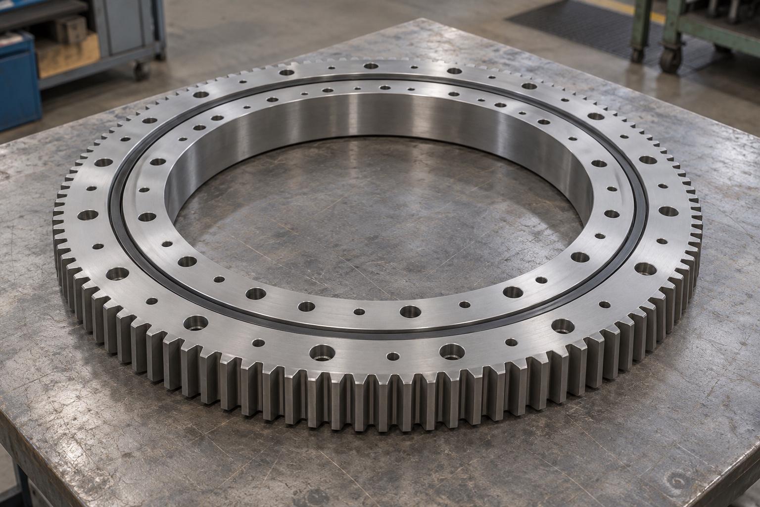
An external gear places teeth around the outside of a ring; an internal gear places them around the bore; a toothless ring leaves the drive arrangement to another component or mechanism. Slewbearingtec offers external gear, internal gear, and toothless slewing bearing configurations. Gear position and rolling element structure are separate choices: a ball or roller design may be considered with different gear arrangements, depending on the actual product.
For a geared bearing, confirm which ring rotates, where the pinion will sit, and whether the surrounding machine has room for the drive and maintenance access. The gear must be checked for the transmitted force, including starting, braking, and possible reverse loading. The pinion, reducer, motor, and brake should be identified separately in the supply scope. A toothed bearing does not, by itself, make a complete slew drive.
Check The Mounting Interface Before Ordering
The outer diameter is only one fit dimension. Compare the inner opening, overall height, both bolt circles, hole sizes and types, locating features, gear data, and the intended rotating ring against the controlled drawing. Two rings with similar envelopes can still be impossible to interchange because of their holes, teeth, clearance, or internal arrangement.
The mounting faces also affect bearing behavior. They need the flatness and stiffness required for the chosen product, with clean contact surfaces and a bolt joint designed for the actual loading. If a flange deflects or has a local gap, the rolling elements and bolts can see loads that a catalog comparison does not reveal. Increasing bolt preload is not a substitute for correcting a poor support surface.
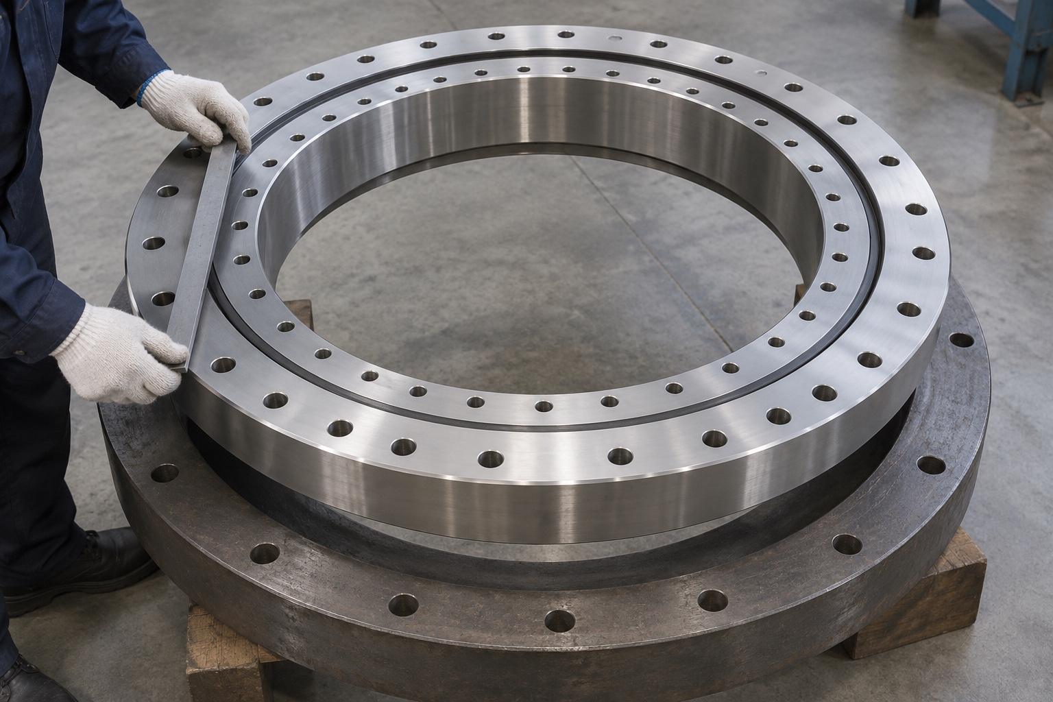
Before installation, confirm the manufacturer’s instructions for the soft zone, bolt tightening, initial lubrication, and gear mesh where applicable. Seals should be checked for damage, and the lubrication plan should cover the raceway and any gear teeth as separate needs. If rotation becomes noisy or drive effort rises unexpectedly, stop and investigate rather than continuing to operate through the symptom.
A Practical Specification To Send
Give the supplier the machine model and bearing location, a drawing of the available interface, the simultaneous axial and radial forces and tilting moments for each operating case, the motion cycle, desired service life, operating environment, and the intended drive layout. For a replacement, include the original part number and drawings where available, but still verify the physical and performance interfaces.
This information allows a specific slewing ring bearing to be assessed as part of the machine, rather than chosen from a name or diameter alone. Slewbearingtec can then discuss a relevant bearing structure and the drawings and checks needed for that application.