SWBTEC


Customized Crossed Roller Slewing Bearing Specialist
The real expert of customized cross roller slewing bearing is not simply selling a standard part. By knocking on the geometry of the internal raceway, fine-tuning the pre-tightening force setting and reforming the structural size, we have specially designed your own rotary joint to solve those extreme loads, severe space restrictions or abnormal environmental requirements.
When you need a huge hollow shaft to walk complicated cables, or need ultra-low outgassing grease in a vacuum environment, or even directly process gears on a pitifully narrow outer ring, you will definitely be disappointed by the spot found in the product catalogue. How do we do it? Get out of the box of standard parts and rub the design of the bearing directly into the “structural genes” of your machine. In fact, it is not difficult to find a factory that can cut out the steel. The real pain point is that you have to find engineers who know the business. They want to know clearly how the deformation of the bearing starting torque and beating accuracy will be killed by thermal expansion and cold contraction and the deformation of the installation base under your actual working conditions.
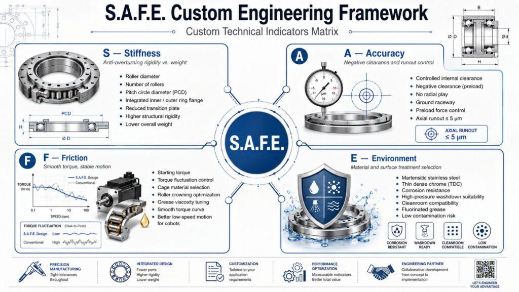
[Hard Core Dry Goods] S.A.F.E. Custom Engineering Framework
Many project managers throw over the demand table is often short of weight, making the proofing time drag on and on. In fact, as long as you apply this set of S.A.F.E. customization rules, you can immediately sort out the technical requirements clearly.
S-Stiffness (Stiffness): A Game between Anti-overturning Moment and Weight
Under heavy load, whether the mechanical arm is accurate or not depends on whether the anti-overturning rigidity is enough. We will pull the stiffness to the limit in a limited space, sticking to the roller diameter, number of rollers and pitch circle diameter (PCD). The most common “magic change” is to make 1 whole mounting flange directly on the inner or outer ring. In this way, the intermediate transition plate is saved, the overall weight is reduced, and the structural rigidity is greatly increased.
A- Precision (Accuracy): The Art of Beating and Negative Clearance
If you want high precision, you have to control the internal clearance. For example, medical imaging equipment, it is necessary to engage in strict negative clearance (pre-tightening) to eliminate the return gap. We will specially grind the raceway, accurately hold the pre-tightening force, ensure that there is absolutely no radial gap, and at the same time press the axial runout to within 5 microns.
F-Friction (Friction): Tame Torque Fluctuation
The starting torque determines how big a motor you want to match, and also determines whether the joint turns smoothly. Heavy preload does have high stiffness, but the friction torque will also take off in situ. What should we do? We will change the cage material, optimize the convexity curve of the roller, adjust the viscosity of the grease, and try our best to “smooth” the torque curve “. Only in this way, collaborative robots (Cobots) will not have annoying “frustration” (I. e. torque fluctuations) when doing slow micro-operations.
E-Environment (Environment): Material vs. Surface Treatment
Ordinary bearing steel to the operating room of the high-pressure water washing environment quasi rust, into the clean room is a source of pollution. We will select materials according to your usage scenario. For example, martensitic stainless steel is directly applied, or a layer of dense thin chromium (TDC) is plated to prevent corrosion, and even special fluorinated grease is used to ensure that no slag is dropped in the Class 100 clean room.
The pit that the insider often steps on: the rigidity of the installation base does not match.
I ‘ve seen too many things happen when engineers destroy high-precision custom bearings during installation. The biggest culprit? Completely ignores the stiffness of the mating piece (mounting base). Custom cross roller bearings are often thin-walled design, to put it bluntly, before the bolt is tightened, its ring is actually relatively “soft.
If you forcibly bolt a P4 (ultra-high precision) bearing to an aluminum base with uneven surface or insufficient thickness, the bearing will physically deform and “settle” the curved base. As a result, the rollers inside were crushed to death. The starting torque soared instantly, and engineers would often scold the bearing manufacturer at this time: “Your bearing is broken, and you can’t turn!” In order to avoid this big pit, we will definitely review your mating parts design drawings before putting into production. We usually recommend thickening the mounting base or adding a customized guide groove (stop groove) to the bearing design to ensure that it can automatically centering and completely eliminate the deformation introduced by the installation.
Exclusive “magic change” for high-end application scenarios (dry goods collection)
For some special industries, the standard slewing bearing structure can not be used. We will do some special geometric optimization for the following specific mechanical fields.
Surgical Robots and Medical Imaging
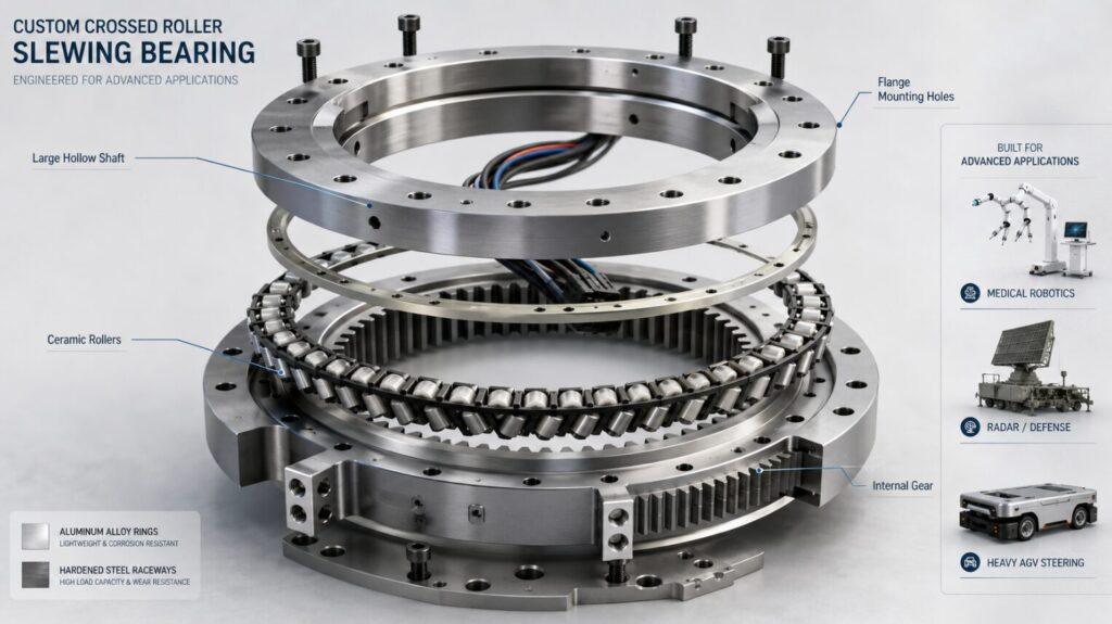
The joints of the surgical arm must be as thin as possible, otherwise the arm is too bloated. We will design custom cross roller bearings to be extremely thin, but also leave a huge inner hole (hollow shaft). This allows engineers to route fiber optics, power cables, and pneumatic lines directly from the center of rotation. We’ll even use ceramic rollers to reduce weight and prevent conduction.
Radar System and Defense Equipment
Military radar pedestals have to withstand extreme hot and cold alternation and high-intensity shock loads. When we design the slewing bearing, we will set aside an expansion gap inside to prevent the bearing from “locking” when the shell contracts in case of cold “. If the requirements for lightweight are extremely high, we will provide a scheme of aluminum ferrule plus hardened steel raceway, which directly reduces the weight by 60% compared with pure solid steel.
Automated Guided Vehicle (AGV)
Steering assemblies for heavy AGVs often require direct drive integration. We will mill the gear directly on the inner or outer ring of the crossed roller bearing. As long as the gear module is perfectly matched with your driving pinion, all those cumbersome secondary transmission gears can be thrown away, directly saving valuable vertical space for AGV with extremely low chassis.
Actual combat case: kill the “Parkinson” of the six-axis surgical mechanical arm”
One medical device manufacturer was tormented by the tiny tremors of the main shoulder joint of their surgical robot. The standard cross roller bearings they originally used had uneven rotating friction, which caused the servo motor to have to go crazy for overload compensation.
In the past, we 1 found out the root of the problem: the roughness of the standard raceway surface, accompanied by their fierce preload, caused serious torque fluctuations. Therefore, we re-customized a set of cross roller bearings for them, with super-precision grinding raceway (surface roughness dry to Ra 0.05), and replaced the standard steel cage with a customized PTFE (polytetrafluoroethylene) spacer.
| Parameters | Standard Bearing | Customized Scheme |
|---|---|---|
| Starting Torque | 2.5 Nm | 0.8 Nm |
| Torque Fluctuation | 15% | 3% |
| Radial Runout | 12 μm | 4 μm |
This customized scheme directly cuts the starting torque by 68%, and the torque fluctuation is almost zero. The surgical robotic arm finally achieved extremely smooth joint movement, and the servo motor could perfectly track the positioning data without even doing any software filtering.
People Also Ask (FAQs)
How long does it usually take to deliver a custom set of cross roller slewing bearings?
Standard catalog stock does ship quickly, but custom engineering requires design, raw material forging and precision grinding. According to the complexity of gear processing or special surface treatment requirements, the delivery period is generally about 45 to 90 days. Of course, rapid prototyping services can help you speed up the pace of early verification.
Can gears be cut out directly on crossed roller bearings?
Absolutely. We often process spur gears, helical gears and even worm gears directly on the inner or outer ring. This integrated design can cut the cumulative assembly error, save space, but also greatly improve the torsional stiffness of the entire transmission system.
What is the preload of the custom bearing?
The preload is calculated based on the stiffness and tolerable friction torque required for your specific application. We use FEA to analyze the radial, axial, and overturning moment loads you apply. A robot with a high load requires a strong negative clearance; but if it is a continuous rotation application, it must use zero clearance or a small positive clearance, otherwise thermal runaway will definitely occur.
What materials are available for anti-corrosion environments?
For medical and food grade environments, we use AISI 440C or high nitrogen martensitic stainless steel to manufacture custom slewing bearings. Or, we do Raydent (Reardon), dense thin chromium (TDC) or nickel plating on standard 50Mn or 42CrMo bearing steel to obtain excellent corrosion protection without sacrificing the bearing capacity.
Why is the starting torque of the custom slewing bearing I just installed outrageous?
The torque soars after installation, rarely because the bearing itself is defective, nine times out of ten because you installed it on an uneven surface. The thin-walled bearing ring was twisted, squeezing the rollers inside. Be sure to remember: the flatness of your mounting structure must match the accuracy rating of this custom bearing.
Can the standard slewing bearing reduce weight?
Of course. We can reduce weight by designing custom cross-sectional dimensions, drilling weight reduction holes in non-load-bearing areas, or using mixed materials. The commonly used 1 method in the aerospace field is: the aluminum alloy shell is embedded with a steel raceway, and the weight drops in a cliff-like manner, while maintaining the integrity of the roller contact.