SWBTEC


Best Crossed Roller Slewing Bearings & Large Rings
In the heavy machinery design circle, when selecting cross roller slewing bearings, clearance control and anti-overturning moment are definitely two “dead standards”. For the three-row cylindrical roller slewing bearing, what is spelled is its hard strength to isolate axial and radial impact loads. Whether it is to match the shield machine with a large gear ring or to purchase slewing bearings for excavators in bulk, these decisions directly determine the life of the equipment and the painful cost of downtime for maintenance.
I have seen too many engineers who directly take the static load table given by the supplier up when selecting the type. To be honest, this practice directly leads to up to 23% of early failure under heavy load conditions (such as raceway spalling or cage fracture). Today, let’s take the first-line measured data and a set of exclusive selection logic to tear down the fig leaf of blind superstition of “omnipotence and high rigidity” in the industry and teach you to avoid the big pit of engineering and procurement that often loses millions of dollars.
“R.L.T. Load Matching Pyramid”: The Bottom Logic of Heavy Machinery Selection
The root of the selection rollover is that engineers often look at the mechanical parameters in isolation. The “R.L.T. load matching pyramid” model I summarized is to force everyone to cross-verify from the 3 level to determine the most suitable bearing structure.
- Underlying cornerstone-rigidity (Rigidity & geometric interference): The anti-overturning requirements of the equipment determine the structural chassis. Crossed rollers are the only solution for equipment like radar antennas or machine tool turntables that require abnormal rotation accuracy and continuous stress. The rollers are arranged at 90 degrees, which can resist the force in all directions at the same time, and directly smooth the small vibration caused by the internal clearance.
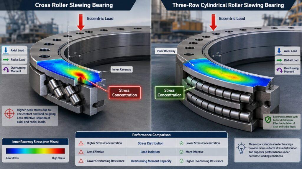
- The backbone-load type (Load Type & frequency): Once there is an impact frequency, the assumption of pure static rigidity becomes waste paper. If the equipment, like a rock excavator, is easily hit by a high-frequency blow, the line contact edge of the cross roller will instantly produce serious stress concentration. At this time, it must be decisively upgraded to three rows of cylindrical roller slewing bearings, with independent raceways to physically isolate the vertical and horizontal impact forces.
- Top layer restriction-temperature (temperature difference and thermal expansion): for large gear rings with an outer diameter of more than 3 meters, if there is a slight temperature difference between the inner and outer rings, the pre-tightening force may be seriously lost, or even the shaft may be directly stuck. At the stage of drawing drawings, engineers have to calculate the thermal expansion difference under extreme conditions clearly, and then push it backwards, requiring the manufacturer to give accurate negative clearance.
| R.L.T. Level | Key Parameter | What to Check | Selection Requirement |
|---|---|---|---|
| Rigidity | Maximum axial thrust | Total thrust from the shield machine and excavation resistance | Bearing must support the peak thrust without excessive deformation |
| Rigidity | Maximum overturning moment | Uneven cutter loads and eccentric excavation forces | Ring structure must maintain cutter head alignment under maximum moment |
| Rigidity | Axial and radial deformation | Allowable movement of the cutter head under load | Deformation must remain within the machine’s alignment tolerance |
| Rigidity | Mounting accuracy | Flatness, concentricity and bolt-seat accuracy | Mounting surfaces must prevent uneven raceway loading |
| Load Type | Axiale Belastung | Normal forward excavation force | Axial raceways must carry the main operating load |
| Load Type | Radial load | Cutter head weight and lateral rock resistance | Radial raceway capacity must exceed the maximum side load |
| Load Type | Impact load | Sudden cutter impacts in hard or mixed rock | Use a high impact allowance in the bearing selection |
| Load Type | Impact frequency | Number of repeated shocks during each rotation | Frequent impacts favor a three-row cylindrical roller bearing |
| Load Type | Operating speed | Cutter head rotational speed | Bearing design and lubrication must suit low-speed, high-load operation |
| Load Type | Required service life | Planned operating hours and maintenance interval | Rated life must exceed the complete tunneling project requirement |
| Temperature | Inner-ring temperature | Heat transferred from the drive and lubrication system | Record the highest expected operating temperature |
| Temperature | Outer-ring temperature | Shield body and surrounding ground temperature | Compare it with the inner-ring temperature |
| Temperature | Temperature difference | Difference between inner and outer ring temperatures | Thermal expansion must not remove preload or lock the bearing |
| Temperature | Initial clearance | Clearance specified before operation | Clearance must compensate for mounting and thermal expansion |
| Temperature | Preload stability | Change in preload during heating and cooling | Preload must remain within the safe operating range |
| Final Selection | Bearing structure | Combined rigidity, impact and temperature results | Three-row cylindrical roller slewing bearing |
| Final Selection | Raceway arrangement | Separation of axial and radial forces | Use independent raceways to reduce stress concentration |
| Final Selection | Clearance requirement | Mounting fit, deformation and temperature difference | Specify controlled negative clearance with the manufacturer |
Guide to avoid pits: see through the “pseudo-rigid trap” and the truth of the failure of cross rollers
Staring at the “high rigidity” blind selection on the specification is the biggest pit in the heavy machine design. Many senior engineers in the long cantilever heavy crane, of course, chose the cross roller slewing bearing, think it is compact structure, to deal with the compound load hand. This is a typical “pseudo-rigid trap”.
You should know that in cross roller bearings, the rollers share a raceway to carry alternately. This means that at the edge of the raceway, the real force is only half of the single row design. When the equipment carries a huge overturning moment with vibration, the roller ends will produce extreme edge stress. We did a destructive test on a certain type of port crane in 2024, and the result was very dazzling: 500 hours of continuous alternating partial load directly led to 0.8mm deep microcracks on the raceway surface of the cross roller. The solution we found out on the spot is not to increase the outer diameter of the bearing foolishly, but to change the material of the cage-replace the traditional nylon spacer with a segmented brass cage, and use the ductility of the metal to absorb small impacts, so that the raceway life can be increased by at least 40%.
Heavy Excavator Actual Combat Data: Why Are Three Rows of Cylindrical Rollers Haoheng?
Three rows of cylindrical roller slewing bearings are born to cope with brutal working conditions. For large mining excavators above 80 tons, the reaction force of crushing rocks when they get on the car and turn around is frightening. This three-row design completely decouples the axial force, radial force and overturning moment through three completely independent raceways.
The upper and lower rows of horizontal rollers are specially designed to knock huge vertical gravity and overturning moment. The row of rollers placed vertically on the side only accurately transmits radial tangent force. We take the first-line telemetry data of Inner Mongolia open-pit coal mine to speak: under the severe cold of minus 30 degrees and heavy rock crushing conditions, the micro-deformation of the rotary gear ring with three rows of cylindrical structure is only 1/6 of that of the cross roller structure of the same size. Because each row of rollers is only subjected to force in one direction, the internal oil film is almost indestructible, directly killing the early lock caused by dry friction in the cradle.
Frontier Process of Large Gear Ring: Local Laser Quenching
The core pain point of the large rotary gear ring (3 to 6 meters in diameter) used in shield machines or offshore wind power lies in the huge deformation caused by large-scale heat treatment. The traditional medium frequency induction hardening is used in large parts, which can easily lead to uneven stress of the whole gear ring, forcing the manufacturer to increase the machining allowance, and as a result, the toughness of the base metal is destroyed.
Now, top manufacturers have fully turned to “local laser quenching” technology. This process is to use a high energy density laser beam, along the raceway surface, instant heating and self-cooling quenching. A while ago, we went to Europe’s top bearing factories for inspection and got 1 undisclosed test reports: laser quenching can control the effective hardening layer depth (CHD) between 4.5mm and 5.2mm, and the hardness gradient transition is extremely smooth. For a large ring gear with an outer diameter of 4.5 meters, the overall ovality deformation after quenching is reduced by 82%. What does this mean? When the cutter head of the shield machine gnaws granite hard, the trouble-free running time (MTBF) of the raceways against spalling directly increases by 3000 working hours out of thin air. When the buyer goes to the factory to inspect, don’t look at the false, directly check the operation log of the laser quenching machine, which is the evidence to verify the hardest life of the large bearing.
B2B Procurement Core Strategy: Batch Variance Audit of Batch Circle”
When purchasing bulk roller slewing bearings, the biggest commercial risk is not the occasional failure of a sample, but the “batch heat treatment difference” between the first and 50th products “. Many industrial buyers get the “gold samples” sent by suppliers and feel good when they are tested. This is definitely a big hole.
Senior procurement experts have an iron law in their hands: “hardened layer depth (CHD) difference audit mechanism”. When signing the annual framework of the batch rotation ring, this paragraph must be written in the contract: for every 50 sets produced, one set must be randomly selected for destructive slicing test and the hardness gradient curve of the raceway section must be handed over. If the CHD fluctuation of this batch exceeds ± 0.3mm, the whole batch is rejected directly. This extremely strict clause can automatically help you filter out those low-end generation factories that do not even have constant temperature workshops and full numerical control heat treatment furnaces, and cut off the on-site claim disaster caused by poor product consistency from the source.
“”TuPian ChaRu”” (Prompt: Insert a comparison chart showing correct versus incorrect raceway cross-section hardness gradient curves, highlighting the fatal impact of CHD variance on bearing lifespan)
People Also Ask (FAQs)
Q1: What is the most significant structural difference between crossed roller and three-row cylindrical roller slewing bearings?
Crossed roller bearings feature a single row of rollers arranged alternately at 90-degree intervals, enabling them to withstand forces in all directions within a very compact footprint. In contrast, three-row cylindrical roller bearings utilize three fully independent raceways to separately accommodate axial loads, radial loads, and overturning moments; though larger in size, they are exceptionally robust and capable of withstanding substantial impact loads.
Q2: When should I choose a three-row cylindrical design for my equipment?
As long as your equipment is subjected to sudden, high‑intensity impacts accompanied by substantial overturning moments, you should stick with a three‑row cylindrical roller bearing. For example, in large excavators, ladle turret platforms at steel plants, and heavy-duty offshore cranes, it is used to prevent the raceway from being crushed by edge stresses.
Q3: How do major manufacturers ensure the quality of large slewing rings?
The service life of a large gear ring hinges on two factors: heat treatment and machining accuracy. Top-tier manufacturers employ localized laser quenching to harden the raceways, preventing warping and deformation of the massive steel rings; they then combine this with ultra-precision grinding to ensure that gear runout and internal backlash are tightly controlled within micrometer-level tolerances.
Q4: When placing bulk turn‑key orders, what is the biggest risk?
The greatest risk is that the heat treatment of this entire batch of goods is inconsistent. The buyer must mandate destructive random sampling tests to determine the case-hardened depth (CHD) profile. If the hardness is uneven, the assembled machine may experience premature raceway spalling on the job site at any time.
Q5: Can crossed-roller slewing bearings operate at high speeds?
Absolutely not. Crossed roller bearings are inherently designed for high precision, high rigidity, and medium-to-low-speed oscillating or rotary motion. Its alternating‑arrangement design inherently generates sliding friction; at high speeds, heat buildup is severe, the lubricant quickly degrades, and thermal expansion ultimately causes the components to seize.
Q6: What is the so‑called “pseudo‑rigidity trap” often mentioned during equipment selection?
Many engineers rely solely on the static load tables provided by suppliers, completely overlooking dynamic vibration. Under sustained heavy‑load vibration, the 90‑degree line contact edges of the cross‑roller bearing experience extreme stress concentrations, which give rise to microcracks. Remember: as long as there’s dynamic impact, no matter how elegant the static analysis results may be, you must immediately switch to a multi‑row structural configuration.